(2016-12-18 Version 2 is now on github. It fixes one bug, makes the code style more consistent, and adds a few additional options for tracking the results.)
It started with a Facebook post from my brother-in-law:
“Okay Facebook, I need your help.
How do you deal with A$$hole’s that live on your street and constantly speed (75 in a 25) up and down the road?
I’ve called the sheriff and they are under manned. I can call the state highway patrol but they are probably in the same boat.
Short of shooting them as they drive by, what do you recommend to get the $#&@! from hell to slow the F down?”
Seventy-five? Really bro? But that got me thinking – could you document the speed of cars on a residential street to add support for police intervention?
Hmmm. I have a Raspberry Pi and a Pi Camera module. Ought to be able to use them to measure a car’s speed. What follows is my implementation of an application that records images with the speed of cars passing in front of the camera.
Requirements:
This is mostly a software implementation so the hardware required is simple:
Raspberry Pi Model 2 (the Pi Model 3 will work even better, but I don’t have one to test)
Pi Camera
The software required is pretty straight forward too:
Raspian
OpenCV
Python
Steps:
Install Raspian on the Raspberry Pi. This has been covered in many places on the net. At this point in time Jessie is the current release and I recommend it for this project.
Install OpenCV 3 and Python 3 on the Pi. Thanks go to Adrian Rosebrock for these great instructions on getting OpenCV and Python installed on a Pi:
http://www.pyimagesearch.com/2015/10/26/how-to-install-opencv-3-on-raspbian-jessie/ My system is using Python 3.4.1 and Opencv 3.1.0 on Raspberry Pi 2 Model B.
Copy the carspeed.py program to your /home/pi directory. My program is based on the motion detection program found on the pyimagesearch.com site with modifications for speed detection. Not only does the program need to detect motion, it needs to time the moving car as it passes across the camera’s field of view, and it needs to know how far the car traveled.
Obviously the horizontal distance that the camera sees at a distance one foot from of the lens is very different than the horizontal distance measured 50 feet from the lens. Using the camera’s field of view and a bit of trigonometry the ‘width’ at any distance from the lens can be computed:
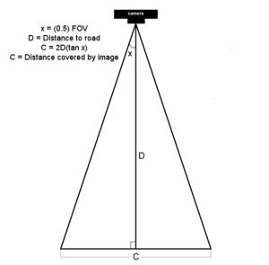
The field of view (FOV) of the Picamera is about 53.5 degrees. Let’s say the road is about 60 feet (D) from our camera. The horizontal distance (C) covered by the image at a distance 60 feet from the lens would be:
2*60+tan(53.5 * 0.5)
120*tan(26.75)
120*0.50
60 feet
So it just happens that the horizontal distance covered by the Picamera’s image is roughly equal to the distance from the lens. If you are 10 feet from the lens, the image is about 10 feet across, 47 feet from the lens, about 47 feet across, and so on.
Of course, other cameras may have a different field of view and won’t have this easy to determine correspondence.
Once the horizontal distance is known, dividing it by the number of pixels in the width of the frame gives the distance each pixel represents. The speed can be calculated from the time it takes for an object to traverse the pixels.
This is what we will ask the motion detection part of the program to do:
- detect motion using the logic presented at the pyimagesearch site
- begin a timer
- track the moving object until it reaches the opposite side of the frame.
- calculate the speed
- save a picture of the image labeled with the speed calculated
The first version of the program was tested by pointing the camera at the street outside my front window. It immediately ran into a problem – the program worked too well. It tracked birds as they flew by, squirrels searching for food in the front yard, and my neighbor opening his garage door.
The program was supposed to watch the street, not the whole neighborhood!
I added logic allowing a mouse to be used to draw a box bounding the area of the image to monitor. That enhancement worked and eliminated nearly all of the extraneous motion detection.
https://gfycat.com/PerfectBonyAplomadofalcon
But the program was having difficulty with cars that were traveling 35+ miles per hour. A car at that speed traveled through the monitored area so quickly that two or more readings were not possible. I profiled the program and found that displaying the image on the screen with the imshow and waitKey() commands was slowing the image processing. A quick code change stopped the image from updating while the car passed through the monitored area. It is a bit strange to see a car enter the frame, hit the edge of the monitored area and disappear until it exits the monitored area, but that modification sped up the processing 2 fold and allowed measurement of higher speeds. From my testing, it looks like the program is accurate to within +/- 1 for speeds up to 40 mph. Cars going faster than that are still recorded but the speed is less accurate since the car passes through the frame so quickly. The program is limited to processing one car at a time, so if you live on a busy highway, it won’t give accurate results. The Raspberry Pi 3 was announced while this post was being added. Given its increased processing power, measurement should be more accurate when recording higher speeds.
Usage
Point the Picamera at the road. Before you run carspeed.py, modify the constant DISTANCE to the distance from the front of the Picamera lens to the middle of the road. You may also need to adjust the vflip and hflip to match you camera’s orientation.
Run from a terminal with:
python carspeed.py
Use a mouse to draw a rectangle around the area you wish to monitor. I recommend a height just sufficient to capture the whole car and a width about one half the frame, centered. Press ‘c’ and the program will begin monitoring the road.
As cars pass through the monitored area, an image will be written to disk with the speed.
Exit with a press of the ‘q’ key.
The Car Speed Program
The program code can be downloaded from here. What follows is a description of the carspeed.py logic.
# CarSpeed Version 2.0

# import the necessary packages
from picamera.array import PiRGBArray
from picamera import PiCamera
import time
import math
import datetime
import cv2
The program starts with the import of packages used.
# place a prompt on the displayed image
def prompt_on_image(txt):
    global image
    cv2.putText(image, txt, (10, 35),
    cv2.FONT_HERSHEY_SIMPLEX, 0.35, (0, 0, 255), 1)

# calculate speed from pixels and time
def get_speed(pixels, ftperpixel, secs):
    if secs > 0.0:
        return ((pixels * ftperpixel)/ secs) * 0.681818
    else:
        return 0.0

# calculate elapsed seconds
def secs_diff(endTime, begTime):
    diff = (endTime - begTime).total_seconds()
    return diff

# record speed in .csv format
def record_speed(res):
    global csvfileout
    f = open(csvfileout, 'a')
    f.write(res+"\n")
    f.close
Next, a few methods and functions are defined. The method “prompt_on_image” simply formats and displays a message on the image. The function “get_speed” returns the speed based on the number of pixels traversed in a given time (substitue 3.6 for the 0.681818 value if you are working with meters and kph rather than feet and mph.) And finally, the function “secs_diff” returns the number of seconds between two times.
# mouse callback function for drawing capture area
def draw_rectangle(event,x,y,flags,param):
    global ix,iy,fx,fy,drawing,setup_complete,image, org_image, prompt

    if event == cv2.EVENT_LBUTTONDOWN:
        drawing = True
        ix,iy = x,y

    elif event == cv2.EVENT_MOUSEMOVE:
        if drawing == True:
            image = org_image.copy()
            prompt_on_image(prompt)
            cv2.rectangle(image,(ix,iy),(x,y),(0,255,0),2)

    elif event == cv2.EVENT_LBUTTONUP:
        drawing = False
        fx,fy = x,y
        image = org_image.copy()
        prompt_on_image(prompt)
        cv2.rectangle(image,(ix,iy),(fx,fy),(0,255,0),2)
The draw_rectangle method handles the mouse events that are used to define the monitored area of the image. It simply lets the user draw a rectangle on the image. The image is refreshed from the original so that the rectangle expands as the mouse moves. If this isn’t done, the mouse moves result in a solid, filled-in rectangle as the rectangles are drawn one on top of the other.
# define some constants
DISTANCE = 76  #<---- enter your distance-to-road value here
MIN_SPEED = 0  #<---- enter the minimum speed for saving images
SAVE_CSV = False  #<---- record the results in .csv format in carspeed_(date).csv

THRESHOLD = 15
MIN_AREA = 175
BLURSIZE = (15,15)
IMAGEWIDTH = 640
IMAGEHEIGHT = 480
RESOLUTION = [IMAGEWIDTH,IMAGEHEIGHT]
FOV = 53.5    #<---- Field of view
FPS = 30
SHOW_BOUNDS = True
SHOW_IMAGE = True
Next comes the definition of constants used in the program. You will need to estimate the distance from the camera to the center of the road and enter it in the DISTANCE constant in line 58. You can specify the minumum speed required before images are saved, and whether the speeds should be saved in a .csv file for analyzing later. The values in THRESHOLD, MIN_AREA and BLURSIZE were what worked best during testing.
# the following enumerated values are used to make the program more readable
WAITING = 0
TRACKING = 1
SAVING = 2
UNKNOWN = 0
LEFT_TO_RIGHT = 1
RIGHT_TO_LEFT = 2
I prefer using enumerated values to make program easier to read. This section defines the ones used. The first three monitor the current state of the tracking process. The next two define the direction of movement on the image. The values assigned are not significant.
# calculate the the width of the image at the distance specified
frame_width_ft = 2*(math.tan(math.radians(FOV*0.5))*DISTANCE)
ftperpixel = frame_width_ft / float(IMAGEWIDTH)
print("Image width in feet {} at {} from camera".format("%.0f" % frame_width_ft,"%.0f" % DISTANCE))
That completes the initialization of the program’s constants and methods. Now it is time to calculate the frame width and the ft per pixel. Note: the same logic works for a distance defined in meters – it just results in meters per pixel.
# state maintains the state of the speed computation process
# if starts as WAITING
# the first motion detected sets it to TRACKING

# if it is tracking and no motion is found or the x value moves
# out of bounds, state is set to SAVING and the speed of the object
# is calculated
# initial_x holds the x value when motion was first detected
# last_x holds the last x value before tracking was was halted
# depending upon the direction of travel, the front of the
# vehicle is either at x, or at x+w
# (tracking_end_time - tracking_start_time) is the elapsed time
# from these the speed is calculated and displayed

state = WAITING
direction = UNKNOWN
initial_x = 0
last_x = 0

#-- other values used in program
base_image = None
abs_chg = 0
mph = 0
secs = 0.0
ix,iy = -1,-1
fx,fy = -1,-1
drawing = False
setup_complete = False
tracking = False
text_on_image = 'No cars'
prompt = ''
The initialization of global variables used throughout the program comes next.
# initialize the camera. Adjust vflip and hflip to reflect your camera's orientation
camera = PiCamera()
camera.resolution = RESOLUTION
camera.framerate = FPS
camera.vflip = True
camera.hflip = True

rawCapture = PiRGBArray(camera, size=camera.resolution)
# allow the camera to warm up
time.sleep(0.9)
And the initialization of the Picamera.
# create an image window and place it in the upper left corner of the screen
cv2.namedWindow("Speed Camera")
cv2.moveWindow("Speed Camera", 10, 40)
We’ll want to see that the program is processing, so a window is created and moved to the upper left corner of the display.
# call the draw_rectangle routines when the mouse is used
cv2.setMouseCallback('Speed Camera',draw_rectangle)

# grab a reference image to use for drawing the monitored area's boundry
camera.capture(rawCapture, format="bgr", use_video_port=True)
image = rawCapture.array
rawCapture.truncate(0)
org_image = image.copy()

if SAVE_CSV:
    csvfileout = "carspeed_{}.cvs".format(datetime.datetime.now().strftime("%Y%m%d_%H%M"))
    record_speed('Date,Day,Time,Speed,Image')
else:
    csvfileout = ''

prompt = "Define the monitored area - press 'c' to continue"
prompt_on_image(prompt)

# wait while the user draws the monitored area's boundry
while not setup_complete:
    cv2.imshow("Speed Camera",image)

    #wait for for c to be pressed
    key = cv2.waitKey(1) & 0xFF

    # if the `c` key is pressed, break from the loop
    if key == ord("c"):
        break
To keep extraneous movement from triggering speed calculations, the user must define the area of the image that should be monitored by the program. This is accomplished by sending mouse events to the method draw_rectangle. In line 134, the program captures one image that will be used for drawing. This image is duplicated with the image.copy() statement. The image is refreshed with the original image as the rectangle is drawn. If the image wasn’t refreshed, the user would see a solid green rectangle drawn, rather than a green outline. The program displays an image and then waits for the user to draw the rectangle around the monitored area. When the user is done, they press the ‘c’ key to continue.
# the monitored area is defined, time to move on
prompt = "Press 'q' to quit"

# since the monitored area's bounding box could be drawn starting
# from any corner, normalize the coordinates

if fx > ix:
    upper_left_x = ix
    lower_right_x = fx
else:
    upper_left_x = fx
    lower_right_x = ix

if fy > iy:
    upper_left_y = iy
    lower_right_y = fy
else:
    upper_left_y = fy
    lower_right_y = iy

monitored_width = lower_right_x - upper_left_x
monitored_height = lower_right_y - upper_left_y

print("Monitored area:")
print(" upper_left_x {}".format(upper_left_x))
print(" upper_left_y {}".format(upper_left_y))
print(" lower_right_x {}".format(lower_right_x))
print(" lower_right_y {}".format(lower_right_y))
print(" monitored_width {}".format(monitored_width))
print(" monitored_height {}".format(monitored_height))
print(" monitored_area {}".format(monitored_width * monitored_height))
The user can start drawing the rectangle from any corner, so once the monitored area is defined, the initial and final x and y points are normalized so that they can be used in calculating direction and distance. The values that result are displayed in the terminal.
# capture frames from the camera (using capture_continuous.
#   This keeps the picamera in capture mode - it doesn't need
#   to prep for each frame's capture.

for frame in camera.capture_continuous(rawCapture, format="bgr", use_video_port=True):
    #initialize the timestamp
    timestamp = datetime.datetime.now()

    # grab the raw NumPy array representing the image
    image = frame.array

    # crop area defined by [y1:y2,x1:x2]
    gray = image[upper_left_y:lower_right_y,upper_left_x:lower_right_x]

    # convert the fram to grayscale, and blur it
    gray = cv2.cvtColor(gray, cv2.COLOR_BGR2GRAY)
    gray = cv2.GaussianBlur(gray, BLURSIZE, 0)

    # if the base image has not been defined, initialize it
    if base_image is None:
        base_image = gray.copy().astype("float")
        lastTime = timestamp
        rawCapture.truncate(0)
        cv2.imshow("Speed Camera", image)

    # compute the absolute difference between the current image and
    # base image and then turn eveything lighter gray than THRESHOLD into
    # white
    frameDelta = cv2.absdiff(gray, cv2.convertScaleAbs(base_image))
    thresh = cv2.threshold(frameDelta, THRESHOLD, 255, cv2.THRESH_BINARY)[1]

    # dilate the thresholded image to fill in any holes, then find contours
    # on thresholded image
    thresh = cv2.dilate(thresh, None, iterations=2)
    (_, cnts, _) = cv2.findContours(thresh.copy(), cv2.RETR_EXTERNAL,cv2.CHAIN_APPROX_SIMPLE)
Finally we are to the meat of the program. Using capture_continuous, the program repeatedly grabs a frame and operates on it. Capture_continuous is used so that the Picamera doesn’t go through the initialization process required when capturing one frame at a time. The image is cropped in line 205 to the area that the user defined to monitor. Using the logic discussed on the pyimagesearch site, the image is converted to grayscale and blurred. The first time through, the program saves the image as base_image. Base_image is then used to compare to the current image and see what has changed. At this point, any differences between the captured image and the base_image are represented by blobs of white in the threshold image.
    # look for motion
    motion_found = False
    biggest_area = 0

    # examine the contours, looking for the largest one
    for c in cnts:
        (x1, y1, w1, h1) = cv2.boundingRect(c)
        # get an approximate area of the contour
        found_area = w1*h1
        # find the largest bounding rectangle
        if (found_area > MIN_AREA) and (found_area > biggest_area):
            biggest_area = found_area
            motion_found = True
            x = x1
            y = y1
            h = h1
            w = w1
Next the program looks for the largest white blob in the threshold image using findContours. We ignore small white blobs, as they can happen at random or may represent a leaf or other small object traveling through the monitored area.The process of grabbing an image and looking for motion continues until motion is detected.
    if motion_found:
        if state == WAITING:
            # intialize tracking
            state = TRACKING
            initial_x = x
            last_x = x
            initial_time = timestamp
            last_mph = 0
            text_on_image = 'Tracking'
            print(text_on_image)
            print("x-chg    Secs      MPH  x-pos width")
        else:
The first time motion is detected, the state changes from WAITING to TRACKING and the initial values of the area-in-motion are recorded.
# compute the lapsed time
            secs = secs_diff(timestamp,initial_time)

            if secs >= 15:
                state = WAITING
                direction = UNKNOWN
                text_on_image = 'No Car Detected'
                motion_found = False
                biggest_area = 0
                rawCapture.truncate(0)
                base_image = None
                print('Resetting')
                continue
if the camera gets bumped or the lighting in monitired area changes dramatically, reset processing after 15 seconds of garbage
(thanks to RawLiquid for suggesting this change)
            if state == TRACKING:
                if x >= last_x:
                    direction = LEFT_TO_RIGHT
                    abs_chg = x + w - initial_x
                else:
                    direction = RIGHT_TO_LEFT
                    abs_chg = initial_x - x
                mph = get_speed(abs_chg,ftperpixel,secs)
                print("{0:4d}  {1:7.2f}  {2:7.0f}   {3:4d}  {4:4d}".format(abs_chg,secs,mph,x,w))
                real_y = upper_left_y + y
                real_x = upper_left_x + x
                # is front of object outside the monitired boundary? Then write date, time and speed on image
                # and save it
                if ((x <= 2) and (direction == RIGHT_TO_LEFT)) \                         or ((x+w >= monitored_width - 2) \
                        and (direction == LEFT_TO_RIGHT)):
                    if (last_mph > MIN_SPEED):    # save the image
                        # timestamp the image
                        cv2.putText(image, datetime.datetime.now().strftime("%A %d %B %Y %I:%M:%S%p"),
                            (10, image.shape[0] - 10), cv2.FONT_HERSHEY_SIMPLEX, 0.75, (0, 255, 0), 1)
                        # write the speed: first get the size of the text
                        size, base = cv2.getTextSize( "%.0f mph" % last_mph, cv2.FONT_HERSHEY_SIMPLEX, 2, 3)
                        # then center it horizontally on the image
                        cntr_x = int((IMAGEWIDTH - size[0]) / 2)
                        cv2.putText(image, "%.0f mph" % last_mph,
                            (cntr_x , int(IMAGEHEIGHT * 0.2)), cv2.FONT_HERSHEY_SIMPLEX, 2.00, (0, 255, 0), 3)
                        # and save the image to disk
                        imageFilename = "car_at_" + datetime.datetime.now().strftime("%Y%m%d_%H%M%S") + ".jpg"
                        # use the following image file name if you want to be able to sort the images by speed
                        #imageFilename = "car_at_%02.0f" % last_mph + "_" + datetime.datetime.now().strftime("%Y%m%d_%H%M%S") + ".jpg"

                        cv2.imwrite(imageFilename,image)
                        if SAVE_CSV:
                            cap_time = datetime.datetime.now()
                            record_speed(cap_time.strftime("%Y.%m.%d")+','+cap_time.strftime('%A')+','+\
                               cap_time.strftime('%H%M')+','+("%.0f" % last_mph) + ','+imageFilename)
                    state = SAVING
                # if the object hasn't reached the end of the monitored area, just remember the speed
                # and its last position
                last_mph = mph
                last_x = x
    else:
        if state != WAITING:
            state = WAITING
            direction = UNKNOWN
            text_on_image = 'No Car Detected'
            print(text_on_image)
With a state of TRACKING, the second and subsequent images with motion are processed to see how far the area-in-motion has changed.The calculation of change in position, line 275 to line 280, depends upon the direction of movement. From right-to-left, the x value of the box bounding the area-in-motion represents the front of the car as it passes through the monitored area. But for motion from left-to-right, the x value won’t change until the entire car has entered the monitored area. The bounding box grows wider as more and more of the car enters the monitored area, until finally the bounding box encloses the rear of the car. Thus the front of the car is x+w where w is the width of the bounding box enclosing the area-in-motion.
Once we have the current position of the front of the car, we calculate the absolute change in pixels from our initial x position in line 277 or line 280. The time interval between the current frame and the initial frame provide the seconds that have lapsed. From time and distance, the speed is calculated in line 281.
This process continues until the area-in-motion’s bounding box reaches the opposite end of the monitored area, line 287. At that point, the date, time are written to the image (line 292), the last speed is displayed centered on the image (line 295 – line 298) and the image is written to disk, line 305. The state is changed to SAVING. The last speed is used since the front of the car would have traveled beyond the monitored boundry, corrupting the x value. The program will continue to see motion as the car exits the monitored area, but since the state is not WAITING or TRACKING, the motion will be ignored.
If no motion is detected, the state returns to WAITING.
    # only update image and wait for a keypress when waiting for a car
    # This is required since waitkey slows processing.
    if (state == WAITING):

        # draw the text and timestamp on the frame
        cv2.putText(image, datetime.datetime.now().strftime("%A %d %B %Y %I:%M:%S%p"),
            (10, image.shape[0] - 10), cv2.FONT_HERSHEY_SIMPLEX, 0.75, (0, 255, 0), 1)
        cv2.putText(image, "Road Status: {}".format(text_on_image), (10, 20),
            cv2.FONT_HERSHEY_SIMPLEX,0.35, (0, 0, 255), 1)

        if SHOW_BOUNDS:
            #define the monitored area right and left boundary
            cv2.line(image,(upper_left_x,upper_left_y),(upper_left_x,lower_right_y),(0, 255, 0))
            cv2.line(image,(lower_right_x,upper_left_y),(lower_right_x,lower_right_y),(0, 255, 0))

        # show the frame and check for a keypress
        if SHOW_IMAGE:
            prompt_on_image(prompt)
            cv2.imshow("Speed Camera", image)

        # Adjust the base_image as lighting changes through the day
        if state == WAITING:
            last_x = 0
            cv2.accumulateWeighted(gray, base_image, 0.25)

        state=WAITING;
        key = cv2.waitKey(1) & 0xFF

        # if the `q` key is pressed, break from the loop and terminate processing
        if key == ord("q"):
            break

    # clear the stream in preparation for the next frame
    rawCapture.truncate(0)

# cleanup the camera and close any open windows
cv2.destroyAllWindows()
The image window is only updated if no motion is detected. If the state is WAITING, the date, time and status is added to the current image. In line 345, the base_image is adjusted slightly to account for lighting changes in the monitored area. These changes result from clouds passing, the changing angle of shadows, blowing leaves, etc.The keyboard is checked for the press of “q” indicating the program should be terminated.

Hi Greg – Thanks for the code and explanation; it was key to me getting my traffic camera working. I’ve finally got around to documenting it https://www.hackster.io/hodgestk/traffic-camera-9d3739
Hope you’re ok with me copying your code and making changes. It started out as a vague idea and grew into quite a lengthy project.
LikeLiked by 2 people
Wow! Great job enhancing the core code. I am so happy to see the concept being revised and expanded. Well done!
LikeLike
Very nice mods. I will have to give it a try and see how easy it is to setup and run headless with a web cam. i did mods to Greg’s code about a year ago to put in front of my daughters school. I was able to setup headless over VNC and then similar to what you’ve done, I allow a config file to be loaded with all the needed settings so restarting and saving data to CSV worked over reboots. My plan was to use OpenCV as you have but never got around to it. Well done!
LikeLiked by 1 person
This thing is very cool. I’ve never really messed with this stuff before, but a friend visited over the holiday and we ordered a camera and got it working.
I tweaked a couple of things to make the fonts work better for me (for example, the green at the bottom didn’t work well for me as that’s grass in my images). I’m not sure if this is a typo or not, but the .csv option actually saved the file as a .cvs file. I fixed that so it would save as an actual .csv and could open it with something like excel (i made a share on the PI and monitor the share from my laptop).
I’m working on getting the accuracy as tight as possible. Would it make it more accurate to make the widest measurement area (green box) as possible? I know you suggest 1/2 the frame but figured I’d ask. I’m about 60′ from the road,and people kind of tend to drive in the middle when only 1 car, which isn’t an issue as this won’t work with 2 cars in frame.
I think i’ll try to get the filename to reflect whether the car was moving right to left or left to right. I already have the speed in the filename. The code knows the direction…I just need some time to figure out the variable to add to the filename. It may be possible to optimize the range to make one more accurate than the other, although you can only do so much as people don’t all drive in the same place.
Again, great job. This is a lot of fun learning about this….and seeing which of my neighbors are the biggest as$hats. 😉
LikeLiked by 1 person
The code has been up for three and a half years and you are the first to spot that typo. Well done! You will need to tweak the tracking box size to meet your situation – balancing the speed of the cars through the frame vs the number of pixels being processed. Wider is more accurate, but will process slower. Thanks for the positive comment.
LikeLike
Hehe, others might have spotted it as I had too and not said anything. I fixed it in my fork where I added the webcam parts and the headless operation via config file loading of tranking box parameters.
It was and is a fun project and your great explanation of operating makes it a great learning opportunity.
LikeLike
“… But the program was having difficulty with cars that were traveling 35+ miles per hour…”
Yes … I don’t know how fast is your program … You need to fix the flow data, try to use two cameras, and get to take in sync the frames from them.
… the first step would be to see how time differences between the frames of the two webcams.
LikeLike
Greg, thank you! This is such a great project. I was able to implement this and I used the data collected to influence my HOA to install additional speed limit signs in the neighborhood where I live.
-Matt
LikeLike
awesome work
LikeLike
Hi Greg this is really cool! I have a NoIR Pi camera on the way and I’m going to try and set this up to run day & night. I might bug you with questions so sorry in advance! 🙂
LikeLike
This looks like a great program. I have everything running but when I run the program I get the picture screen and am able to draw the box for the captured area. When I press “c” I get this error:
Line 228
[it show the values for line 228]
Value Error: need more than 2 values to unpack
Then exits out to the prompt.
What am I missing?
Thanks
LikeLike
See: https://github.com/gregtinkers/carspeed.py/issues/17
LikeLike
Anyone tried to get this working on Android?
LikeLike
Got this working after experiencing similar concerns to others on this thread – people using their street as a ‘rat run’ (https://en.wikipedia.org/wiki/Rat_running). I had a few false starts but I’ve got to say the documentation provided was easy to follow and I feel I’ve really learned a few new skills. Thxs Greg!!
LikeLike
I have adapted this for a Swann NVR. Thanks for this baseline. I measured the distance physically with trashcans rather than the FOV method. Works like a champ.
https://github.com/dengood/SpeedCamSwann
LikeLike
Amazing, will give this a go. I had been considering trying to build something similar for a local A road in the countryside near me, hidden in a wildlife type camera box. I was dreaming of ANPR to create a list of repeat offenders.
LikeLike
Hi,
This used to work well for me, but I had to re-install my raspberryPi and now with opencv being the latest version 4.5.5 I get this error when running, Google searches suggested this is some backward compatibility issue? that the contour function is changed? I can’t figure out how to fix it, any ideas?
File “/home/pi/carspeed/carspeed.py”, line 228, in
(_, cnts, _) = cv2.findContours(thresh,cv2.RETR_TREE,cv2.CHAIN_APPROX_SIMPLE)
ValueError: not enough values to unpack (expected 3, got 2)
Thanks!
LikeLike
Hi,
the interface in openCV 4.4.0 changed. The function cv.findContours() now returns only 2 parameters. So just change the code to
(cnts, _) = cv2.findContours(thresh,cv2.RETR_TREE,cv2.CHAIN_APPROX_SIMPLE)
and you should be good to go (see https://docs.opencv.org/4.4.0/d3/dc0/group__imgproc__shape.html#gadf1ad6a0b82947fa1fe3c3d497f260e0)
LikeLike
Hello, I have the same speeder sproblem in my neighborhood. I am not skilled in electronics, other than to fly and fight in an Apache AH64. Would you please sell me a system to collect data to re-enforce facts with my meeting with civic leaders. Johnny Bower sirbower@yahoo.com
LikeLike
The program was meant to be a proof-of-concept and an educational endeavor. It isn’t a finished product that can be sold. There aren’t any “electronics’ required to implement the program on a Raspberry Pi. Think of it more as following instructions to install programs on a computer. You might be surprised, once you begin to work with a Raspberry Pi, at all you can do with it.
LikeLike