(2016-12-18 Version 2 is now on github. It fixes one bug, makes the code style more consistent, and adds a few additional options for tracking the results.)
It started with a Facebook post from my brother-in-law:
“Okay Facebook, I need your help.
How do you deal with A$$hole’s that live on your street and constantly speed (75 in a 25) up and down the road?
I’ve called the sheriff and they are under manned. I can call the state highway patrol but they are probably in the same boat.
Short of shooting them as they drive by, what do you recommend to get the $#&@! from hell to slow the F down?”
Seventy-five? Really bro? But that got me thinking – could you document the speed of cars on a residential street to add support for police intervention?
Hmmm. I have a Raspberry Pi and a Pi Camera module. Ought to be able to use them to measure a car’s speed. What follows is my implementation of an application that records images with the speed of cars passing in front of the camera.

Requirements:
This is mostly a software implementation so the hardware required is simple:
Raspberry Pi Model 2 (the Pi Model 3 will work even better, but I don’t have one to test)
Pi Camera
The software required is pretty straight forward too:
Raspian
OpenCV
Python
Steps:
Install Raspian on the Raspberry Pi. This has been covered in many places on the net. At this point in time Jessie is the current release and I recommend it for this project.
Install OpenCV 3 and Python 3 on the Pi. Thanks go to Adrian Rosebrock for these great instructions on getting OpenCV and Python installed on a Pi:
http://www.pyimagesearch.com/2015/10/26/how-to-install-opencv-3-on-raspbian-jessie/ My system is using Python 3.4.1 and Opencv 3.1.0 on Raspberry Pi 2 Model B.
Copy the carspeed.py program to your /home/pi directory. My program is based on the motion detection program found on the pyimagesearch.com site with modifications for speed detection. Not only does the program need to detect motion, it needs to time the moving car as it passes across the camera’s field of view, and it needs to know how far the car traveled.
Obviously the horizontal distance that the camera sees at a distance one foot from of the lens is very different than the horizontal distance measured 50 feet from the lens. Using the camera’s field of view and a bit of trigonometry the ‘width’ at any distance from the lens can be computed:
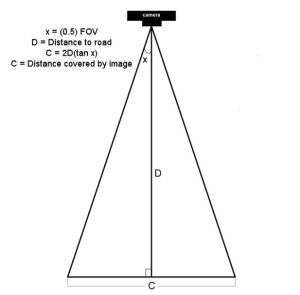
The field of view (FOV) of the Picamera is about 53.5 degrees. Let’s say the road is about 60 feet (D) from our camera. The horizontal distance (C) covered by the image at a distance 60 feet from the lens would be:
2*60+tan(53.5 * 0.5)
120*tan(26.75)
120*0.50
60 feet
So it just happens that the horizontal distance covered by the Picamera’s image is roughly equal to the distance from the lens. If you are 10 feet from the lens, the image is about 10 feet across, 47 feet from the lens, about 47 feet across, and so on.
Of course, other cameras may have a different field of view and won’t have this easy to determine correspondence.
Once the horizontal distance is known, dividing it by the number of pixels in the width of the frame gives the distance each pixel represents. The speed can be calculated from the time it takes for an object to traverse the pixels.
This is what we will ask the motion detection part of the program to do:
- detect motion using the logic presented at the pyimagesearch site
- begin a timer
- track the moving object until it reaches the opposite side of the frame.
- calculate the speed
- save a picture of the image labeled with the speed calculated
The first version of the program was tested by pointing the camera at the street outside my front window. It immediately ran into a problem – the program worked too well. It tracked birds as they flew by, squirrels searching for food in the front yard, and my neighbor opening his garage door.
The program was supposed to watch the street, not the whole neighborhood!
I added logic allowing a mouse to be used to draw a box bounding the area of the image to monitor. That enhancement worked and eliminated nearly all of the extraneous motion detection.
https://gfycat.com/PerfectBonyAplomadofalcon
But the program was having difficulty with cars that were traveling 35+ miles per hour. A car at that speed traveled through the monitored area so quickly that two or more readings were not possible. I profiled the program and found that displaying the image on the screen with the imshow and waitKey() commands was slowing the image processing. A quick code change stopped the image from updating while the car passed through the monitored area. It is a bit strange to see a car enter the frame, hit the edge of the monitored area and disappear until it exits the monitored area, but that modification sped up the processing 2 fold and allowed measurement of higher speeds. From my testing, it looks like the program is accurate to within +/- 1 for speeds up to 40 mph. Cars going faster than that are still recorded but the speed is less accurate since the car passes through the frame so quickly. The program is limited to processing one car at a time, so if you live on a busy highway, it won’t give accurate results. The Raspberry Pi 3 was announced while this post was being added. Given its increased processing power, measurement should be more accurate when recording higher speeds.
Usage
Point the Picamera at the road. Before you run carspeed.py, modify the constant DISTANCE to the distance from the front of the Picamera lens to the middle of the road. You may also need to adjust the vflip and hflip to match you camera’s orientation.
Run from a terminal with:
python carspeed.py
Use a mouse to draw a rectangle around the area you wish to monitor. I recommend a height just sufficient to capture the whole car and a width about one half the frame, centered. Press ‘c’ and the program will begin monitoring the road.
As cars pass through the monitored area, an image will be written to disk with the speed.
Exit with a press of the ‘q’ key.
The Car Speed Program
The program code can be downloaded from here. What follows is a description of the carspeed.py logic.
# CarSpeed Version 2.0

# import the necessary packages
from picamera.array import PiRGBArray
from picamera import PiCamera
import time
import math
import datetime
import cv2
The program starts with the import of packages used.
# place a prompt on the displayed image
def prompt_on_image(txt):
    global image
    cv2.putText(image, txt, (10, 35),
    cv2.FONT_HERSHEY_SIMPLEX, 0.35, (0, 0, 255), 1)

# calculate speed from pixels and time
def get_speed(pixels, ftperpixel, secs):
    if secs > 0.0:
        return ((pixels * ftperpixel)/ secs) * 0.681818
    else:
        return 0.0

# calculate elapsed seconds
def secs_diff(endTime, begTime):
    diff = (endTime - begTime).total_seconds()
    return diff

# record speed in .csv format
def record_speed(res):
    global csvfileout
    f = open(csvfileout, 'a')
    f.write(res+"\n")
    f.close
Next, a few methods and functions are defined. The method “prompt_on_image” simply formats and displays a message on the image. The function “get_speed” returns the speed based on the number of pixels traversed in a given time (substitue 3.6 for the 0.681818 value if you are working with meters and kph rather than feet and mph.) And finally, the function “secs_diff” returns the number of seconds between two times.
# mouse callback function for drawing capture area
def draw_rectangle(event,x,y,flags,param):
    global ix,iy,fx,fy,drawing,setup_complete,image, org_image, prompt

    if event == cv2.EVENT_LBUTTONDOWN:
        drawing = True
        ix,iy = x,y

    elif event == cv2.EVENT_MOUSEMOVE:
        if drawing == True:
            image = org_image.copy()
            prompt_on_image(prompt)
            cv2.rectangle(image,(ix,iy),(x,y),(0,255,0),2)

    elif event == cv2.EVENT_LBUTTONUP:
        drawing = False
        fx,fy = x,y
        image = org_image.copy()
        prompt_on_image(prompt)
        cv2.rectangle(image,(ix,iy),(fx,fy),(0,255,0),2)
The draw_rectangle method handles the mouse events that are used to define the monitored area of the image. It simply lets the user draw a rectangle on the image. The image is refreshed from the original so that the rectangle expands as the mouse moves. If this isn’t done, the mouse moves result in a solid, filled-in rectangle as the rectangles are drawn one on top of the other.
# define some constants
DISTANCE = 76  #<---- enter your distance-to-road value here
MIN_SPEED = 0  #<---- enter the minimum speed for saving images
SAVE_CSV = False  #<---- record the results in .csv format in carspeed_(date).csv

THRESHOLD = 15
MIN_AREA = 175
BLURSIZE = (15,15)
IMAGEWIDTH = 640
IMAGEHEIGHT = 480
RESOLUTION = [IMAGEWIDTH,IMAGEHEIGHT]
FOV = 53.5    #<---- Field of view
FPS = 30
SHOW_BOUNDS = True
SHOW_IMAGE = True
Next comes the definition of constants used in the program. You will need to estimate the distance from the camera to the center of the road and enter it in the DISTANCE constant in line 58. You can specify the minumum speed required before images are saved, and whether the speeds should be saved in a .csv file for analyzing later. The values in THRESHOLD, MIN_AREA and BLURSIZE were what worked best during testing.
# the following enumerated values are used to make the program more readable
WAITING = 0
TRACKING = 1
SAVING = 2
UNKNOWN = 0
LEFT_TO_RIGHT = 1
RIGHT_TO_LEFT = 2
I prefer using enumerated values to make program easier to read. This section defines the ones used. The first three monitor the current state of the tracking process. The next two define the direction of movement on the image. The values assigned are not significant.
# calculate the the width of the image at the distance specified
frame_width_ft = 2*(math.tan(math.radians(FOV*0.5))*DISTANCE)
ftperpixel = frame_width_ft / float(IMAGEWIDTH)
print("Image width in feet {} at {} from camera".format("%.0f" % frame_width_ft,"%.0f" % DISTANCE))
That completes the initialization of the program’s constants and methods. Now it is time to calculate the frame width and the ft per pixel. Note: the same logic works for a distance defined in meters – it just results in meters per pixel.
# state maintains the state of the speed computation process
# if starts as WAITING
# the first motion detected sets it to TRACKING

# if it is tracking and no motion is found or the x value moves
# out of bounds, state is set to SAVING and the speed of the object
# is calculated
# initial_x holds the x value when motion was first detected
# last_x holds the last x value before tracking was was halted
# depending upon the direction of travel, the front of the
# vehicle is either at x, or at x+w
# (tracking_end_time - tracking_start_time) is the elapsed time
# from these the speed is calculated and displayed

state = WAITING
direction = UNKNOWN
initial_x = 0
last_x = 0

#-- other values used in program
base_image = None
abs_chg = 0
mph = 0
secs = 0.0
ix,iy = -1,-1
fx,fy = -1,-1
drawing = False
setup_complete = False
tracking = False
text_on_image = 'No cars'
prompt = ''
The initialization of global variables used throughout the program comes next.
# initialize the camera. Adjust vflip and hflip to reflect your camera's orientation
camera = PiCamera()
camera.resolution = RESOLUTION
camera.framerate = FPS
camera.vflip = True
camera.hflip = True

rawCapture = PiRGBArray(camera, size=camera.resolution)
# allow the camera to warm up
time.sleep(0.9)
And the initialization of the Picamera.
# create an image window and place it in the upper left corner of the screen
cv2.namedWindow("Speed Camera")
cv2.moveWindow("Speed Camera", 10, 40)
We’ll want to see that the program is processing, so a window is created and moved to the upper left corner of the display.
# call the draw_rectangle routines when the mouse is used
cv2.setMouseCallback('Speed Camera',draw_rectangle)

# grab a reference image to use for drawing the monitored area's boundry
camera.capture(rawCapture, format="bgr", use_video_port=True)
image = rawCapture.array
rawCapture.truncate(0)
org_image = image.copy()

if SAVE_CSV:
    csvfileout = "carspeed_{}.cvs".format(datetime.datetime.now().strftime("%Y%m%d_%H%M"))
    record_speed('Date,Day,Time,Speed,Image')
else:
    csvfileout = ''

prompt = "Define the monitored area - press 'c' to continue"
prompt_on_image(prompt)

# wait while the user draws the monitored area's boundry
while not setup_complete:
    cv2.imshow("Speed Camera",image)

    #wait for for c to be pressed
    key = cv2.waitKey(1) & 0xFF

    # if the `c` key is pressed, break from the loop
    if key == ord("c"):
        break
To keep extraneous movement from triggering speed calculations, the user must define the area of the image that should be monitored by the program. This is accomplished by sending mouse events to the method draw_rectangle. In line 134, the program captures one image that will be used for drawing. This image is duplicated with the image.copy() statement. The image is refreshed with the original image as the rectangle is drawn. If the image wasn’t refreshed, the user would see a solid green rectangle drawn, rather than a green outline. The program displays an image and then waits for the user to draw the rectangle around the monitored area. When the user is done, they press the ‘c’ key to continue.
# the monitored area is defined, time to move on
prompt = "Press 'q' to quit"

# since the monitored area's bounding box could be drawn starting
# from any corner, normalize the coordinates

if fx > ix:
    upper_left_x = ix
    lower_right_x = fx
else:
    upper_left_x = fx
    lower_right_x = ix

if fy > iy:
    upper_left_y = iy
    lower_right_y = fy
else:
    upper_left_y = fy
    lower_right_y = iy

monitored_width = lower_right_x - upper_left_x
monitored_height = lower_right_y - upper_left_y

print("Monitored area:")
print(" upper_left_x {}".format(upper_left_x))
print(" upper_left_y {}".format(upper_left_y))
print(" lower_right_x {}".format(lower_right_x))
print(" lower_right_y {}".format(lower_right_y))
print(" monitored_width {}".format(monitored_width))
print(" monitored_height {}".format(monitored_height))
print(" monitored_area {}".format(monitored_width * monitored_height))
The user can start drawing the rectangle from any corner, so once the monitored area is defined, the initial and final x and y points are normalized so that they can be used in calculating direction and distance. The values that result are displayed in the terminal.
# capture frames from the camera (using capture_continuous.
#   This keeps the picamera in capture mode - it doesn't need
#   to prep for each frame's capture.

for frame in camera.capture_continuous(rawCapture, format="bgr", use_video_port=True):
    #initialize the timestamp
    timestamp = datetime.datetime.now()

    # grab the raw NumPy array representing the image
    image = frame.array

    # crop area defined by [y1:y2,x1:x2]
    gray = image[upper_left_y:lower_right_y,upper_left_x:lower_right_x]

    # convert the fram to grayscale, and blur it
    gray = cv2.cvtColor(gray, cv2.COLOR_BGR2GRAY)
    gray = cv2.GaussianBlur(gray, BLURSIZE, 0)

    # if the base image has not been defined, initialize it
    if base_image is None:
        base_image = gray.copy().astype("float")
        lastTime = timestamp
        rawCapture.truncate(0)
        cv2.imshow("Speed Camera", image)

    # compute the absolute difference between the current image and
    # base image and then turn eveything lighter gray than THRESHOLD into
    # white
    frameDelta = cv2.absdiff(gray, cv2.convertScaleAbs(base_image))
    thresh = cv2.threshold(frameDelta, THRESHOLD, 255, cv2.THRESH_BINARY)[1]

    # dilate the thresholded image to fill in any holes, then find contours
    # on thresholded image
    thresh = cv2.dilate(thresh, None, iterations=2)
    (_, cnts, _) = cv2.findContours(thresh.copy(), cv2.RETR_EXTERNAL,cv2.CHAIN_APPROX_SIMPLE)
Finally we are to the meat of the program. Using capture_continuous, the program repeatedly grabs a frame and operates on it. Capture_continuous is used so that the Picamera doesn’t go through the initialization process required when capturing one frame at a time. The image is cropped in line 205 to the area that the user defined to monitor. Using the logic discussed on the pyimagesearch site, the image is converted to grayscale and blurred. The first time through, the program saves the image as base_image. Base_image is then used to compare to the current image and see what has changed. At this point, any differences between the captured image and the base_image are represented by blobs of white in the threshold image.
    # look for motion
    motion_found = False
    biggest_area = 0

    # examine the contours, looking for the largest one
    for c in cnts:
        (x1, y1, w1, h1) = cv2.boundingRect(c)
        # get an approximate area of the contour
        found_area = w1*h1
        # find the largest bounding rectangle
        if (found_area > MIN_AREA) and (found_area > biggest_area):
            biggest_area = found_area
            motion_found = True
            x = x1
            y = y1
            h = h1
            w = w1
Next the program looks for the largest white blob in the threshold image using findContours. We ignore small white blobs, as they can happen at random or may represent a leaf or other small object traveling through the monitored area.The process of grabbing an image and looking for motion continues until motion is detected.
    if motion_found:
        if state == WAITING:
            # intialize tracking
            state = TRACKING
            initial_x = x
            last_x = x
            initial_time = timestamp
            last_mph = 0
            text_on_image = 'Tracking'
            print(text_on_image)
            print("x-chg    Secs      MPH  x-pos width")
        else:
The first time motion is detected, the state changes from WAITING to TRACKING and the initial values of the area-in-motion are recorded.
# compute the lapsed time
            secs = secs_diff(timestamp,initial_time)

            if secs >= 15:
                state = WAITING
                direction = UNKNOWN
                text_on_image = 'No Car Detected'
                motion_found = False
                biggest_area = 0
                rawCapture.truncate(0)
                base_image = None
                print('Resetting')
                continue
if the camera gets bumped or the lighting in monitired area changes dramatically, reset processing after 15 seconds of garbage
(thanks to RawLiquid for suggesting this change)
            if state == TRACKING:
                if x >= last_x:
                    direction = LEFT_TO_RIGHT
                    abs_chg = x + w - initial_x
                else:
                    direction = RIGHT_TO_LEFT
                    abs_chg = initial_x - x
                mph = get_speed(abs_chg,ftperpixel,secs)
                print("{0:4d}  {1:7.2f}  {2:7.0f}   {3:4d}  {4:4d}".format(abs_chg,secs,mph,x,w))
                real_y = upper_left_y + y
                real_x = upper_left_x + x
                # is front of object outside the monitired boundary? Then write date, time and speed on image
                # and save it
                if ((x <= 2) and (direction == RIGHT_TO_LEFT)) \                         or ((x+w >= monitored_width - 2) \
                        and (direction == LEFT_TO_RIGHT)):
                    if (last_mph > MIN_SPEED):    # save the image
                        # timestamp the image
                        cv2.putText(image, datetime.datetime.now().strftime("%A %d %B %Y %I:%M:%S%p"),
                            (10, image.shape[0] - 10), cv2.FONT_HERSHEY_SIMPLEX, 0.75, (0, 255, 0), 1)
                        # write the speed: first get the size of the text
                        size, base = cv2.getTextSize( "%.0f mph" % last_mph, cv2.FONT_HERSHEY_SIMPLEX, 2, 3)
                        # then center it horizontally on the image
                        cntr_x = int((IMAGEWIDTH - size[0]) / 2)
                        cv2.putText(image, "%.0f mph" % last_mph,
                            (cntr_x , int(IMAGEHEIGHT * 0.2)), cv2.FONT_HERSHEY_SIMPLEX, 2.00, (0, 255, 0), 3)
                        # and save the image to disk
                        imageFilename = "car_at_" + datetime.datetime.now().strftime("%Y%m%d_%H%M%S") + ".jpg"
                        # use the following image file name if you want to be able to sort the images by speed
                        #imageFilename = "car_at_%02.0f" % last_mph + "_" + datetime.datetime.now().strftime("%Y%m%d_%H%M%S") + ".jpg"

                        cv2.imwrite(imageFilename,image)
                        if SAVE_CSV:
                            cap_time = datetime.datetime.now()
                            record_speed(cap_time.strftime("%Y.%m.%d")+','+cap_time.strftime('%A')+','+\
                               cap_time.strftime('%H%M')+','+("%.0f" % last_mph) + ','+imageFilename)
                    state = SAVING
                # if the object hasn't reached the end of the monitored area, just remember the speed
                # and its last position
                last_mph = mph
                last_x = x
    else:
        if state != WAITING:
            state = WAITING
            direction = UNKNOWN
            text_on_image = 'No Car Detected'
            print(text_on_image)
With a state of TRACKING, the second and subsequent images with motion are processed to see how far the area-in-motion has changed.The calculation of change in position, line 275 to line 280, depends upon the direction of movement. From right-to-left, the x value of the box bounding the area-in-motion represents the front of the car as it passes through the monitored area. But for motion from left-to-right, the x value won’t change until the entire car has entered the monitored area. The bounding box grows wider as more and more of the car enters the monitored area, until finally the bounding box encloses the rear of the car. Thus the front of the car is x+w where w is the width of the bounding box enclosing the area-in-motion.
Once we have the current position of the front of the car, we calculate the absolute change in pixels from our initial x position in line 277 or line 280. The time interval between the current frame and the initial frame provide the seconds that have lapsed. From time and distance, the speed is calculated in line 281.
This process continues until the area-in-motion’s bounding box reaches the opposite end of the monitored area, line 287. At that point, the date, time are written to the image (line 292), the last speed is displayed centered on the image (line 295 – line 298) and the image is written to disk, line 305. The state is changed to SAVING. The last speed is used since the front of the car would have traveled beyond the monitored boundry, corrupting the x value. The program will continue to see motion as the car exits the monitored area, but since the state is not WAITING or TRACKING, the motion will be ignored.
If no motion is detected, the state returns to WAITING.
    # only update image and wait for a keypress when waiting for a car
    # This is required since waitkey slows processing.
    if (state == WAITING):

        # draw the text and timestamp on the frame
        cv2.putText(image, datetime.datetime.now().strftime("%A %d %B %Y %I:%M:%S%p"),
            (10, image.shape[0] - 10), cv2.FONT_HERSHEY_SIMPLEX, 0.75, (0, 255, 0), 1)
        cv2.putText(image, "Road Status: {}".format(text_on_image), (10, 20),
            cv2.FONT_HERSHEY_SIMPLEX,0.35, (0, 0, 255), 1)

        if SHOW_BOUNDS:
            #define the monitored area right and left boundary
            cv2.line(image,(upper_left_x,upper_left_y),(upper_left_x,lower_right_y),(0, 255, 0))
            cv2.line(image,(lower_right_x,upper_left_y),(lower_right_x,lower_right_y),(0, 255, 0))

        # show the frame and check for a keypress
        if SHOW_IMAGE:
            prompt_on_image(prompt)
            cv2.imshow("Speed Camera", image)

        # Adjust the base_image as lighting changes through the day
        if state == WAITING:
            last_x = 0
            cv2.accumulateWeighted(gray, base_image, 0.25)

        state=WAITING;
        key = cv2.waitKey(1) & 0xFF

        # if the `q` key is pressed, break from the loop and terminate processing
        if key == ord("q"):
            break

    # clear the stream in preparation for the next frame
    rawCapture.truncate(0)

# cleanup the camera and close any open windows
cv2.destroyAllWindows()
The image window is only updated if no motion is detected. If the state is WAITING, the date, time and status is added to the current image. In line 345, the base_image is adjusted slightly to account for lighting changes in the monitored area. These changes result from clouds passing, the changing angle of shadows, blowing leaves, etc.The keyboard is checked for the press of “q” indicating the program should be terminated.

Pingback: Raspberry Pi As Speed Camera | Hackaday
Pingback: Raspberry Pi As Speed Camera | wisdomparliament
Pingback: Raspberry Pi As Speed Camera | Geek Casual
Pingback: Raspberry Pi As Speed Camera – Sloppy Laughs
This is an interesting project, kudos for developing it!
I wonder – it seems that the limiting factor in measuring higher speeds is the processing that’s done between captures. The Pi can capture VGA-resolution video at up to 90 fps; what if you used the image processing simply to detect the arrival of an object, then grabbed a second or two of 90 fps video? You could then step through the video frames at your leisure, without losing temporal resolution. At 90 fps and a 50-foot field of view, you could measure up to 68 mph, with a resolution of ~1.5 mph. I don’t know of course; there might be issues of how quickly you could switch from still- to video-recording, the video might be (probably is) in some compressed format that’d need unpacking, etc, etc, but the application doesn’t need real-time response; a delay of 10 seconds between passage of the car and display of results would likely be perfectly acceptable. (Unless you wanted to fire a paintball, deploy a spike strip, etc, but you could always set that up down the road and trigger by radio 😉
Of course, you could just increase the FOV with a wide angle lens. I’m sure you could fine one that was RPi-specific, but this guy adapted a cellphone lens with a little hacking:
http://www.raspberrypi-spy.co.uk/2013/06/cheap-interchangeable-lenses-for-the-raspberry-pi-camera-module/
(One thing to watch for with a wide-angle adapter would be geometric distortion. A fisheye adapter would be undesirable for that reason…)
Kudos again on the clever project!
LikeLiked by 1 person
Thank you for posting this! I have all the necessary components laying about and will try and build this very soon. If it works out for the Pi2 I’ll swap into a Pi3 and let you know.
LikeLiked by 1 person
Great keep it up
LikeLike
Hey,
great posting! Tried a lot of different tools to measure the speed at my road – same situation as your brother in law… Will try it this week!
Tried this one http://ramseyelectronics.com/cmp/sg7/default.html and this one http://www.limpkin.fr/index.php?post/2013/08/09/Making-the-electronics-for-a-%247-USD-doppler-motion-sensor – but not what i expected.
One thought about performance, would it get improved if just use a b/w image instead of rgb??
I really dont need color images 😀
Best regards
LikeLike
Pingback: Car Speed Detector using OpenCV, Raspberry Pi and a Pi Camera | Do It Yourself India Magazine
Nice, thx for sharing !
You need now to add a number plate analyzer and mail alarm directly linked to the police 😀
Regards
LikeLike
Excellent, thank you for sharing this! I’ve been contemplating a similar setup for a few years, since moving into a house on a suburban corner where I watch maybe 1 in 50 cars actually STOP at the stop sign. I’m going to try modifying this to be a sort of “stop sign cam”.
LikeLike
This project is really amazing, thanks for documenting it.
I am going to reproduce your setup for the horrific intersection we have here in Berkeley, where stop signs are merely suggestions, and there are near misses every day.
I hope everyone put one of these up on their street, to address the sociopathy of the “Its My World” kind of drivers that are so pervasive.
LikeLike
I once saw the results of monitoring a traffic prone intersection by an auto company’s research group. They had a continuously recording system with enough memory to buffer a minute of video. They also had a microphone nearby. With some voice-recognition like listening they were able to identify the sound of a crash and would dump to disk the 30 seconds before and after the crash. They had some examples of bad driving that would be hilarious except for being real. Sounds like doing this is now doable by everyone with a rPi
LikeLike
Just got this running on a RPI3. I had to fall back to opencv 3.0.0 as I couldn’t get 3.1.0 to compile properly. Also, it only works in python3, but that’s ok. My street is only 35′ from camera to center of street, but just got a shot of the mail truck going by at 16mph 🙂
LikeLike
I’ve been trying to install this, well opencv first, for a few days on a fresh install of Jessie. Always fails trying to get the libjpeg files. Will persevere though.
LikeLike
This might sound dumb and trivial, but every time I see a pi in action, I wonder what case it has, and how the camera is held in position. I’m still trying to figure out a convenient way to set my equipment up.
Great, interesting work!
LikeLike
I have a Pi case with removable sides from MCM. I found blue “tak” mounting putty a great way to hold the camera to the outside of the case. The camera can easily be removed and re-positioned as needed. To get the “tak” off the camera, just blot it with a larger piece of the stuff.
LikeLike
Thanks for the reply! It actually hasn’t really occurred to me to use soft materials and adhesives for this purpose.
LikeLike
I just ordered one of these. I plan on mounting a solar panel on top, and monitoring it’s voltage / temp / avg cpu usage while it’s in use.
I’m also working on a headless version, so I can maybe put these together in a solar powered mesh network (ambitious, I know) that forwards the files to a central location 🙂
LikeLike
Just got this running on a raspi 2. Great project, loving it so far, and been reading through the code all afternoon.
Things I needed to do:
1. I had to run this simple script, because I had make errors with installing opencv.
https://www.raspberrypi.org/forums/viewtopic.php?f=32&t=122555
2. I had to explicitly call python3 when running it because of cv2 dependency.
“python3 carspeed.py” was necessary as well.
“python carspeed.py” was not be able to find the “cv2” dependency for me.
Thanks so much for your hard work! I’m working on a headless version of the code. I’m new to computer science, so I will officially fork when I learn how to use git 😛
Thanks again!
LikeLike
Did you set this all up in a virtualenv?
LikeLike
Yes. I followed the pyimagesearch site’s instructions for the installation of Python 3 and OpenCV 3. The pyimagesearch site is excellent for getting started with the Pi and OpenCV programs. I highly recommend it.
LikeLike
Awesome. That’s what I’m in the middle of. I just wasn’t sure if you went the virtualenv route or just directly ran everything.
LikeLike
I find that it works flawlessly for a time, then gets into a loop and just writes a file whenever it can, once every 5 seconds until i stop the program and restart.
I have made the boundary box so that there isn’t any moving shrubbery or anything like that is there anything.
LikeLike
I saw that behavior when the camera moved, or there was a large difference between the base_image and the current (empty) image. Things like fast moving clouds can cause false readings. Make sure the Picamera is held steady. You can adjust the sensitivity using THRESHOLD, MIN_AREA and BLURSIZE. If you want the base image to respond to lighting changes more quickly, you can play with the value in accumulateWeighted, line 304.
LikeLike
Ah brilliant, thanks for the reply. since i last reset it, it seems to be playing ball nicely. i think i adjusted the box a little smaller than the last few times.
I know it’s not the initial purpose, though (i’m sure if i look through the code) is there a way of forcing the coordinates of a boundary rather than manually specifying, as at the moment i’m having to remote in and restart and select the boundary. would be simpler (in this instance) to have a default one and a gui one.
LikeLike
The selection of the bounding box occurs from line 135 to 163. If you commented those lines out and set upper_left_x, lower_right_x, upper_left_y, lower_right_y to the coordinates that you want, you could avoid the manual drawing of the boundary. However, keep in mind that if you change the location of the camera, you will need to adjust those coordinates.
LikeLike
“I saw that behavior when the camera moved…”
I’m so glad you said that. I’ve got the camera taped up on the window with electrical tape at the moment, and it doesn’t hold too well (have a case coming in soon). I’ve been scratching my head trying to figure out why it gets stuck in a “tracking” loop, where it won’t log actual cars passing by.
LikeLike
Greg, thank you very much. that’s perfect, i’ve also a cron running every 10 minutes uploading the files to dropbox. automation is always nice.
Cheers.
LikeLike
Great post. I was looking at using infrared beams with passive IR detectors to do the same project. IR is very accurate and works day or night. I picked up a cheap IR flashlight that looks down on to the road. The beam bounces off the road (reflected) or any passing object. The passive IR detectors sit in an array next to the beam to pick up the return signal. Much like radar, the beam reflection is used to calculate the speed of the vehicle.
I would be interested in using your idea for the photographic evidence needed for law enforcement. Thanks for the great information.
LikeLike
Could you give more info on this? I thought about doing this too, but never pulled the trigger. It looks like you have one emitter and several receivers?
LikeLike
Hello Greg, I’m trying to run your program on rpi3 with opencv 3.1.0 python3 installed. But when I run this program it gives me a error massage said that: (Speed Camera:759): Gtk-WARNING *:cannot open display
Do you have any idea about how to fix this problem? Thanks!
LikeLike
It looks like it is an issue with permissions and remote access. I’d suggest a quick search for that error message. Best of luck getting it resolved.
LikeLike
Problem solved, I was trying to run the program under CLI. But I found that it need to be running under Jessie terminal.
LikeLike
Sorry for newb question, but seems like when I define the area, I am getting this fabulous error. Any help?
Image width in feet 61 at 61 from camera
Monitored area:
upper_left_x 34
upper_left_y 172
lower_right_x 628
lower_right_y 282
monitored_width 594
monitored_height 110
monitored_area 65340
Traceback (most recent call last):
File “carspeed.py”, line 213, in
(_, cnts, _) = cv2.findContours(thresh.copy(), cv2.RETR_EXTERNAL,cv2.CHAIN_APPROX_SIMPLE)
ValueError: need more than 2 values to unpack
LikeLike
I’m guessing that you have installed opencv 2.something. There was a change in the number of parameters returned by findContours in OpenCV 3.0.
Change (_, cnts, _) to read (cnts, _) and I think it might continue to process. (If I remember correctly, this popped up for me when upgrading to run on OpenCV 3.0 the first time.) Have fun!
LikeLike
Bingo! Yep apparently doing OpenCV the lazy way via apt-get gets you lazy results.
My next battle is accuracy. For some reason speeds posted are about 25Mph slower than I now people are doing. I set the distance right. This is on Pi 3
LikeLike
Check the running display of what the program is calculating. Are you seeing multiple calculations for the car as it moves through the monitored are? You may want to reduce the width of the monitored area to increase processing speed. There are things that can cause the program to calculate speed incorrectly: some cars have the same grey-scale value as the background, or if it is a sunny day and there are shadows on the street and cast by the cars, the car’s shadow can be detected and then disappear when it merges with the shadow on the street. The last value in the “–>” message is the width of the car. If that is not relatively consistent, it could be one of these issues.
LikeLike
Reducing size of the window definitely improved the processing. In general, is there a good rule of thumb for what is the optimal placement/distance from the road? I can place it 61′ or about 135′ from the road. I have it now at 61
LikeLike
I don’t have the option of placing the camera more than 70 feet from the road, so I can’t say. Experiment and share the results!
LikeLike
hi, how can i change mph to kps? like:
if SPEED_MPH:
speed_units = “mph”
speed_conv = 1.0 * px_to_mph
else:
speed_units = “kph”
speed_conv = 1.609344 * px_to_mph
LikeLike
Line 265 is where the speed is written to the image. Just use your last calculation as kph = 1.609344 * last_mph and write kph to the image instead of last_mph.
LikeLike
If I changed 0.6 to 3.6 in line 18, do I also need to specify the DISTANCE as meters ?
LikeLike
Yes. Understand that I did not test with kilometers per hour. You may need to do some testing to see if the calculations are correct.
LikeLike
Hi everyone!
Because I don’t have the Pi-Hardware, I have to setup this application using a Microsoft USB LifeCam. Is there a workaround: for the import ‘PiRGBArray’ and ‘PiCamera’ in row 2 & 3? Another problem is to import cv2 in line 7.
My installation is: VS2015, OpenCV-3.1.0 and Python-3.4.
Grek: Thank you for the nice project !
LikeLike
Thanks for this post. My cat was recently killed by a speeding car on my road and the council say to me that there is no danger on my road and therefore they will not lower the speed limits. I’m going to try this little side project to give a little proof to it all, maybe then they will change things on my road.
LikeLike
As a next step, trigger a camera flash if the speed is over the limit + safety threshold… the people who speed regularly will start wondering if the police installed a speed camera in that section of the road, and will slow down in fear of the second ticket.
LikeLike
A high score board would be a nice bit of public shaming.
LikeLike
What would it take to be able to capture speeds up to 100 mph in a highway setting? Perhaps from the vantage of an overpass. Im not technically inclined enough to know what the requirements are.
LikeLike
Tracking cars at that speed is probably beyond this implementation. However, the Pi camera is capable of recording at much higher frame rates when no processing is being performed. Perhaps splitting the video capture into a separate thread could give you what you want. The Pyimagesearch website has some examples of doing this.
LikeLike
Awesome!
LikeLike
Having the same problem on my street. Just curious if this evidence is admissible and if law enforcement were able to take action or is the speeding problem still present?
LikeLike
I don’t think this is admissible just because the thing is not officially approved. Also there is a clash of interest if you as a private citizen do “this”.
By missconfiguring the hardware/script the speed can easily be calculated wrong.
I just got a 110 Kmh speed shot which is not possible.
LikeLike
Pingback: Car Speed Detector made with Raspberry Pi #piday #raspberrypi @Raspberry_Pi « Adafruit Industries – Makers, hackers, artists, designers and engineers!
Although a cool and interesting project, it falls just short of being useful. It would be useful if the offending drivers/vehicles could be issued citations. It would be interesting if you could set up another camera to take a picture of the license plate at some point in the cycle and put it on the picture as well so the picture could be sent to the authorities. Whether they listen or not is another question. Put it in a mailbox, or on a tree or in a “newspaper” box near the street and trigger it with the wireless module between the Pi boards. If nothing else it would give law enforcement a reason to sit on the street and catch their own money makers.
LikeLike
nice post. I used to live in wooster!!!
LikeLike
Hi Greg
I am very interested in using this project to check the speed of scooters on Amsterdam bike paths. Thanks to crazy legislation, some scooters are now allowed to maskerade as bikes. They are supposed to ride max 25 k/hr, but most go much faster. I want to try hanging your device from the fifth floor, about 50 feet above the bike path.
Martin
LikeLike
As long as the monitored area doesn’t contain multiple bikes, you should be successful. I look forward to hearing how well it works.
LikeLike
This is a great contribution. I’m very new to OpenCV and trying to get the software from GitHub working. I’m using a desktop and a Logitech C920 camera that I’d like to get this running on. I’m trying to understand how to replace the PiCamera piece and wondering if you have any pointers on this? I can get access to the camera using cv2.VideoCapture(1) but I’m not sure how to set or read the FPS. I think abstracting out the camera would be ideal and make this code readily useful to others. If I knew enough about how to do this myself I would but I’m just learning and seeing if you or anyone else might know how to do this easily.
LikeLike
great post. I am looking to do the same on my road. But I dont care so much about photos of cars. I want to document time and speeds and graph it out. This way i can present to my local PD or city counsel. I would love to use doppler, because it would get both east and west cars but cant seem to find an easy how to on it. If anyone has thoughts on that or anything else that would great.
LikeLike
This project is super cool. How may i do the same thing using C++?
LikeLike
Thank you SO much for your post!! I’ve been wanting to do something like this for a while, but was contemplating radar or laser/infrared trips. Your idea is much more simple and works great!! I took your idea (and your code!) and modified it slightly so that it inserts the information into a database (postgres). Now I have the data to crunch and distribute to neighbors and authorities to see how big the problem is in addition to the photos of the cars. AWESOME!
LikeLike
Hi Gene, where can we find your code?
LikeLike
Not OP, but here’s an implementation I did a while back. Check out the db package – it uses PostgreSQL and SQLAlchemy
https://github.com/minorsecond/carspeed.py
LikeLike
Greg,
Just wanted to show you something. I took your code and combined it with PostgreSQL and R to create an shiny app. It plots graphs of daily speed and whatnot. It’s pretty intermittent at the moment due to a crappiest WiFi connection to the raspberry pi, but check it out. I can provide the code if anyone is interested.
http://ridgmar.racing
LikeLike
That’s a pretty nice implementation. is it easy enough to set up all the pre required programs/services? wouldn’t mind giving this a go.
Cheers
LikeLike
Thanks, Pete.
It takes a bit of setup. I can point you in the right direction. I’ve changed some of my code and haven’t committed it to Github.com yet so I’ll do that and then update you.
What OS would you run it on? This runs on Shiny Server, which uses R. The dependencies are:
-> PostgreSQL
-> R
-> Shiny Server
There are a few dependencies within R as well, but I can’t remember them off the top of my head.
LikeLike
That’s very impressive. I’ve been working with R and Shiny professionally for some years now and have just got my hands on a Raspberry Pi 3 and am interested in how to combine them. Since you’ve offered, I’d be interested in how you got this set up and coding for the Shiny interface.
LikeLiked by 1 person
I too am very eager to try this. I hope Robert can help.
LikeLike
Jason,
I’ve cleaned up the repo a bit. The code is still a little messy though. You can find it here:
https://github.com/minorsecond/carspeed.py/tree/master
There are some instructions in the Readme but it may be lacking. Basically, you:
1. set up openCV just like Greg has instructed
2. Clone the repo to both your Raspberry Pi and the Shiny Server computer
2. Set up PostgreSQL on the Pi
3. Install Shiny on another machine (I’ve tried to compile it on the Pi 2 but it’s a no-go)
4. Change the IP address in downloader.sh on the Shiny Server computer to the IP address of the Raspberry Pi
5. Set up a chron job to run downloader.sh every n minutes. This script queries the Pi and builds an RDS file locally.
I can write up a blog post so I can be more descriptive this weekend if you like.
LikeLike
Hi Robert
We are very interested in implementing this to check the speed of scooters on Amsterdam bike paths. There are obviously times when other road users (cylcists) muddy the water, but often a fast scooter is way ahead of the rest (and we want to know how many go father than 15 mph).
Please let us know when and where we can find the source code?
LikeLike
It’s currently on Github, but it’s not very pretty. You can use it as is, but I was planning on pending a few days commenting things and refactoring some of the Python code. I also plan on completing the Readme.
https://github.com/minorsecond/carspeed.py
LikeLike
I replied before (or tried to, at least), but I don’t know if it went through.
The code is here:
https://github.com/minorsecond/carspeed.py
However, I was planning on going through and refactoring it so that it’s easier to understand. You can use it as-is if you want, but I am going to begin cleaning it up today and will probably be finished by this weekend.
If you have any questions, don’t hesitate to shoot me an email.
LikeLike
I replied a while back but it didn’t every appear for some reason. I replied to Jason above but I’ll post it here too to make sure you see it.
I’ve cleaned up the repo a bit. The code is still a little messy though. You can find it here:
https://github.com/minorsecond/carspeed.py/tree/master
There are some instructions in the Readme but it may be lacking. Basically, you:
1. set up openCV just like Greg has instructed
2. Clone the repo to both your Raspberry Pi and the Shiny Server computer
2. Set up PostgreSQL on the Pi
3. Install Shiny on another machine (I’ve tried to compile it on the Pi 2 but it’s a no-go)
4. Change the IP address in downloader.sh on the Shiny Server computer to the IP address of the Raspberry Pi
5. Set up a chron job to run downloader.sh every n minutes. This script queries the Pi and builds an RDS file locally.
I can write up a blog post so I can be more descriptive this weekend if you like.
LikeLike
My apologies – I had email issues a while back and looks like I missed the notification that you post needed approval. Thanks for enhancing and improving carspeed. Your continued support is appreciated.
LikeLike
Greetings Ross,
Thanks for the quick reply! Looking forward to digging into this in the next couple of days and let you know how it goes. Re: a blog post – I certainly wouldn’t complain if you put one up. 🙂
LikeLike
what if using usb camera?
LikeLike
Greg and Ross, many thanks for your great efforts writing this code!
I’ve just been playing around with it (5th time this year someone crashed out the corner onto bicycle path’s which is schoolroute…).
But (it’s dark now, so will test tomorrow again), it appears there is quite a variation in the calculated speed of one car. Some cars will get 4/5 chg, others get 9/10, ranging from 26 to 78 in same ‘shot’. Sometimes a negative value is calculated as well. Any suggestions?
Also sometimes the code goes bazerk 🙂 Constantly reading/seeing changes, although nothing is happening on the street 🙂
Last question; out of the multiple changes that are registered per car, which one is written to the image? Lot of images now have a value that doesn’t reflect what console displays (maybe an average?).
LikeLike
I think the inconsistent number of readings is because the process gets preempted by other things Linux is doing. However, and to answer your last question, the speed is calculated from the time the car first enters the frame to the time it exists, so the number of readings theoretically should not matter.
Since the image is changed to grey-scale for identifying the front of the car, any shadows in the image can really mess up the calculations. The camera will detect the shadow of a car before the car reaches the monitored area. Then if there are any shadows in the monitored area, the car’s shadow disappears in it and it looks like the car has shrunk in size -throwing off the readings. I don’t know if that is what you are seeing, but it is one possibility.
The readings on the console reflect the calculation from the initial entry into the frame. The bazerk readings occur when the image changes faster than the program can adjust. Since it is comparing pixels, that could be a very minor bump to the camera, clouds changing the shadows, etc. Although I haven’t had a chance to post it, I’ve got version 2.0 that resets itself. I would be happy to forward it to you if you would like.
LikeLike
Thanks a lot for your incredibly quick reply Greg!
It may indeed be caused by me being logged in to VNC and remotely watching (over WiFi). I will play around with framesize to see what works.
There is an LED-streetlight right above the target area I’ve selected, so there is no shadow. Although maybe headlight-beams may be throwing it of?
Trying to see if I have some code-skills left anywhere in the balding head to see if I can get it to only save pictures for cars over certain limit/threshold 🙂
Very much like to be guinea pig for v2.0!
LikeLike
The strange thing is that there’s incredible variation in the calculation, can’t attach a screenshot, but it sometimes varies from -12 to +56, all in the same tracking. The camera is placed quite stable in windowsill.
Quite often a zero or negative reading is printed to the image/photo, hence me wondering which value of the tracking is written 🙂
LikeLike
One thing I played around with was creating a list of speed readings while the vehicles was in-frame, and then taking the median of the list. This seemed to help a bit with some of the readings that were very high or low.
LikeLike
I haven’t found much success tracking cars at night. You are correct that the lights throw the calculations off – the headlights will merge with the streetlight. Carspeed really works best during the day.
Running VNC will effect the processing speed. Best to let it run for a while, then review the results. I think the results will be much more consistent.
LikeLike
And another quick question; would it make sense to increase FPS to 60? That’s what latest module supports. When I change the constant in code, it appears to ‘zoom’ the picture, which is weird 🙂
LikeLike
That is strange behavior. I don’t remember anything like that happening when I was testing with different frame rates, though I didn’t test a 60 fps.
LikeLike
Specs of latest cam (or at least one I have):
Rpi camera (v2.1) Sony IMX219
Lens: f=3.04 mm, f/2.0
Angle of view: 62.2 x 48.8 degrees
Applicable mode:
– 7 – VGA binned and cropped (1000 pixels off left/right, 752 pixels off top/bottom before binning), 40 to 90fps (120fps if overclocked)
LikeLike
Greg, have any ways to deal with two cars crossing at the same time crossed your mind, by chance? I think this might be impossible to handle since, even if you did have two bounding boxes, they would might merge once they crossed. I’ve thought about disabling the output if there is direction detected from both sides but I’m not sure.
LikeLike
It would take some pretty tricky programming to recognize which car was where in the frame to actually compute their speed. The current program tracks the largest body, so to disable output you would need to change the program to count all the objects greater than a certain size and if the count is greater than one, wait for the monitored area to clear.
LikeLike
Greg, thought i’d compile all the frames that i’ve kept from when i ran the program as a test back in April.
Cheers Pete
LikeLiked by 1 person
This is great fun to watch. Obviously carSpeed has difficulty with multiple targets, but it appears to have nailed the speed of several cyclists (and the lawn mower!)
LikeLike
Ah thanks, yes it made me chuckle, especially catching me mowing the lawn.
i had to have it pointing at an angle so that messed calculations up, as if i had it pointing straight ahead then the neighbours opposite would trip it over if they were parking, carSpeed would wait for them to exit the frame.
The bounding box went from the top of the fence (by the person in that first frame, to their small gate due) to moving foliage being picked up.
LikeLike
Hi Pete,
That looks very interesting. I using the standard software made by Greg or have you tweaked it? BTW – it sounds like you have Dutch roots? In Amsterdam we are working on a project to measure the speed of scooters on the bike paths.
regards, Martin
LikeLike
Hi Martin, I am using the standard software as my coding has a lot to be desired. the only things that were amended were normal ones, resolution, distance etc.
Somewhere down the line i have dutch ancestry, i was born in Zimbabwe so there is definite dutchness.
That sounds like a good use of the program, good luck with it.
Pete
LikeLike
Hi Greg, thanks a lot for this nice project. I use it to learn more about OpenCV and Python. And get an idea how fast cars are going by my house 😉
I noticed a few things while playing around with the code:
I run it on a Pi 3 and measure how many frames per second (FPS) are processed. When I run your original code, I just get up to 7 FPS. When I disable the windows, I get up to 9 FPS. This is not as fast as I expected. The FPS, that are specified in the code are used to setup the camera, but calculation and image output take apparently quite some time.
I also noticed, that sometimes the speed varies greatly when a car passes by. I think the reason is in the code where you examine the contours. You use the line
(x, y, w, h) = cv2.boundingRect(c)
in a for loop to find the biggest contour. This is fine, but later on you use x, y, w, h for speed and direction calculations. This is not correct, as x, y, w, h are from the LAST contour in the array, not the BIGGEST one. So this can screw up the speed and direction calculations. This becomes obvious for me at night, when the camera only sees the head and tail lights. First the head light comes into view and is tracked, then the tail light comes into view, which is apparently detected as the last contour, causing the speed to become negative.
I had to fiddle around with the MIN_AREA value quite a bit. My camera is very close to the street (about 20 feet) so using your value will detect even leaves on the street. In addition, I have to mess around with pixels rather than real units (feet/meters). So besides the FOV, which is defined for horizontal view, I added also a FOV for vertical view (for standard raspberry camera it is 41.41°). With this information, I can calculate not only width, but also hight in units. Finally, I was able to define my MIN_AREA in square foot rather than pixels. Using this information, you would also be able to calculate the cross sectional area of an object (and thus determine if you deal with a pedestrian, a car or truck).
Thanks again for this great project.
LikeLike
Good catch! You can see that this has been up on the web for several months and you are the first to catch that. It works most of the time because there is only one area or the larger area is last in the array of contours. But you are correct, that if there are two areas and the smaller is found after the larger, the x and y will apply to the last element of the cnts array.
I think this will be a quick fix starting at line 219 (untested)
====================================================
# examine the contours, looking for the largest one
for c in cnts:
(x1, y1, w1, h1) = cv2.boundingRect(c)
# get an approximate area of the contour
found_area = w1*h1
# find the largest bounding rectangle
if (found_area > MIN_AREA) and (found_area > biggest_area):
biggest_area = found_area
x = x1
y = y1
w = w1
motion_found = True
=======================================
I think it is time for an update, as I have several other fixes that have been suggested. Coming soon!
LikeLike
Your fix will do the trick. I think the problem was apparent to me, because my camera is very close to the street and I did not change the MIN_AREA value at first. This increased the numbers of contours and hence, the chances of seeing the problem.
LikeLike
I want to make the files with speed first so I can sort them easily. How do I do that?
LikeLike
The current version of CarSpeed doesn’t write to a file, but if you have a modified version, look for a line that with “write” in it (probably f.write). Python uses that command to output to a file. You should be able to change the order of the variables to get it to output in the order that you want.
LikeLike
Sorry, I meant the filename of the jpg should start with speed then date.jpg. I need an example as im not fammiliar with python.
LikeLike
Line 268 is where the file name is created. Try this – change
cv2.imwrite(“car_at_”+datetime.datetime.now().strftime(“%Y%m%d_%H%M%S”)+”.jpg”,
image)
to
cv2.imwrite(“car_at_%.0f” % last_mph+”_”+datetime.datetime.now().strftime(“%Y%m%d_%H%M%S”)+”.jpg”,
image)
That should add the speed to the start of the filename.
LikeLike
If you change Greg’s last line to cv2.imwrite(“%02.0f” % last_mph+”_”+datetime.datetime.now().strftime(“%Y%m%d_%H%M%S”)+”.jpg”,
image), then your file will always start with 2 digits like “04_2016113_161734,jpg”. This makes sorting easier. If you just use “%2.0f” it will just use 2 digits but without the leading 0. Instead a space will be used. That makes sorting more difficult.
LikeLike
Hi,
# call the draw_rectangle routines when the mouse is used
cv2.setMouseCallback(‘Speed Camera’,draw_rectangle)
# grab a reference image to use for drawing the monitored area’s boundry
camera.capture(rawCapture, format=”bgr”, use_video_port=True)
image = rawCapture.array
rawCapture.truncate(0)
org_image = image.copy()
i want to apply above part using recorded video.
i tried to follow with the above code but failed.
i used
camera=cv2.videocapture(video.mp4)
grabbed, frame = camera.read()
Then i stucked here. i tried to grab reference image but i got several errors.
Please help me .
LikeLike
Hi Greg, I’m excited about this project, bought a Pi Camera, upgraded to Raspbian and successfully installed Open CV using the excellent pyimagesearch guide. However, on running I get an error that appears to reference the GTK dev library installed during the Open CV guide ($ sudo apt-get install libgtk2.0-dev). If you can spare a moment I’d be very grateful for any pointers.
This is the error I get:
$ source ~/.profile
$ workon cv
(cv) $ python3 carspeed.py
Image width in feet 3 at 3 from camera
OpenCV Error: Unspecified error (The function is not implemented. Rebuild the library with Windows, GTK+ 2.x or Carbon support. If you are on Ubuntu or Debian, install libgtk2.0-dev and pkg-config, then re-run cmake or configure script) in cvNamedWindow, file /home/pi/opencv-3.0.0/modules/highgui/src/window.cpp, line 516
Traceback (most recent call last):
File “carspeed.py”, line 119, in
cv2.namedWindow(“Speed Camera”)
cv2.error: /home/pi/opencv-3.0.0/modules/highgui/src/window.cpp:516: error: (-2) The function is not implemented. Rebuild the library with Windows, GTK+ 2.x or Carbon support. If you are on Ubuntu or Debian, install libgtk2.0-dev and pkg-config, then re-run cmake or configure script in function cvNamedWindow
I’ve repeated the GTK install, tried a few other things, but says it’s already installed.
Yours in hope!
LikeLike
After installing the GTK, did you repeat the compile and installation of opencv? From the description on the pyimagesearch site, it looks like the library is used to “compile the highgui sub-module of OpenCV, which allows us to display images to our screen and build simple GUI interfaces”
Also perhaps this link may help you.
Sorry I can’t be of more help – I’m not really an opencv installation expert – I just follow the pyimagesearch instructions.
LikeLike
Thanks for getting back Greg, yep compile and installation of Open CV went fine, just as described on pyimagesearch – i’ll check out the link, not sure where the .pc files are, but will keep exploring!
LikeLike
Hi, sorry if you already replied this, is it possible to measuere the speed from an “almost front” point (like a post on the side of the road) instead of sideways?
I want to try and make a display for my neightbourhood 🙂
Sorry for my english!
Thanks! 😀
LikeLike
If the car is not moving perpendicular to the camera, the speed calculation would be much more difficult. Would it be possible, yes. Would it be easy, no.
LikeLike