(2016-12-18 Version 2 is now on github. It fixes one bug, makes the code style more consistent, and adds a few additional options for tracking the results.)
It started with a Facebook post from my brother-in-law:
“Okay Facebook, I need your help.
How do you deal with A$$hole’s that live on your street and constantly speed (75 in a 25) up and down the road?
I’ve called the sheriff and they are under manned. I can call the state highway patrol but they are probably in the same boat.
Short of shooting them as they drive by, what do you recommend to get the $#&@! from hell to slow the F down?”
Seventy-five? Really bro? But that got me thinking – could you document the speed of cars on a residential street to add support for police intervention?
Hmmm. I have a Raspberry Pi and a Pi Camera module. Ought to be able to use them to measure a car’s speed. What follows is my implementation of an application that records images with the speed of cars passing in front of the camera.

Requirements:
This is mostly a software implementation so the hardware required is simple:
Raspberry Pi Model 2 (the Pi Model 3 will work even better, but I don’t have one to test)
Pi Camera
The software required is pretty straight forward too:
Raspian
OpenCV
Python
Steps:
Install Raspian on the Raspberry Pi. This has been covered in many places on the net. At this point in time Jessie is the current release and I recommend it for this project.
Install OpenCV 3 and Python 3 on the Pi. Thanks go to Adrian Rosebrock for these great instructions on getting OpenCV and Python installed on a Pi:
http://www.pyimagesearch.com/2015/10/26/how-to-install-opencv-3-on-raspbian-jessie/ My system is using Python 3.4.1 and Opencv 3.1.0 on Raspberry Pi 2 Model B.
Copy the carspeed.py program to your /home/pi directory. My program is based on the motion detection program found on the pyimagesearch.com site with modifications for speed detection. Not only does the program need to detect motion, it needs to time the moving car as it passes across the camera’s field of view, and it needs to know how far the car traveled.
Obviously the horizontal distance that the camera sees at a distance one foot from of the lens is very different than the horizontal distance measured 50 feet from the lens. Using the camera’s field of view and a bit of trigonometry the ‘width’ at any distance from the lens can be computed:
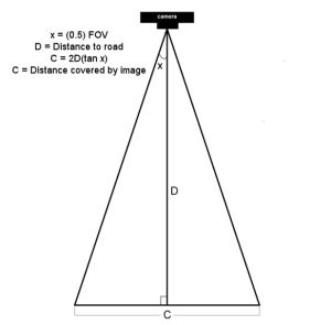
The field of view (FOV) of the Picamera is about 53.5 degrees. Let’s say the road is about 60 feet (D) from our camera. The horizontal distance (C) covered by the image at a distance 60 feet from the lens would be:
2*60+tan(53.5 * 0.5)
120*tan(26.75)
120*0.50
60 feet
So it just happens that the horizontal distance covered by the Picamera’s image is roughly equal to the distance from the lens. If you are 10 feet from the lens, the image is about 10 feet across, 47 feet from the lens, about 47 feet across, and so on.
Of course, other cameras may have a different field of view and won’t have this easy to determine correspondence.
Once the horizontal distance is known, dividing it by the number of pixels in the width of the frame gives the distance each pixel represents. The speed can be calculated from the time it takes for an object to traverse the pixels.
This is what we will ask the motion detection part of the program to do:
- detect motion using the logic presented at the pyimagesearch site
- begin a timer
- track the moving object until it reaches the opposite side of the frame.
- calculate the speed
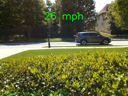
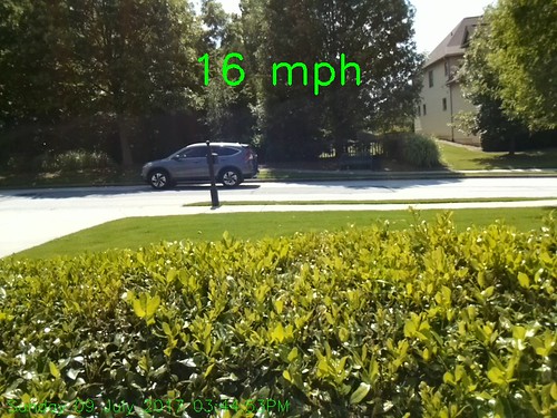
- save a picture of the image labeled with the speed calculated
The first version of the program was tested by pointing the camera at the street outside my front window. It immediately ran into a problem – the program worked too well. It tracked birds as they flew by, squirrels searching for food in the front yard, and my neighbor opening his garage door.
The program was supposed to watch the street, not the whole neighborhood!
I added logic allowing a mouse to be used to draw a box bounding the area of the image to monitor. That enhancement worked and eliminated nearly all of the extraneous motion detection.
https://gfycat.com/PerfectBonyAplomadofalcon
But the program was having difficulty with cars that were traveling 35+ miles per hour. A car at that speed traveled through the monitored area so quickly that two or more readings were not possible. I profiled the program and found that displaying the image on the screen with the imshow and waitKey() commands was slowing the image processing. A quick code change stopped the image from updating while the car passed through the monitored area. It is a bit strange to see a car enter the frame, hit the edge of the monitored area and disappear until it exits the monitored area, but that modification sped up the processing 2 fold and allowed measurement of higher speeds. From my testing, it looks like the program is accurate to within +/- 1 for speeds up to 40 mph. Cars going faster than that are still recorded but the speed is less accurate since the car passes through the frame so quickly. The program is limited to processing one car at a time, so if you live on a busy highway, it won’t give accurate results. The Raspberry Pi 3 was announced while this post was being added. Given its increased processing power, measurement should be more accurate when recording higher speeds.
Usage
Point the Picamera at the road. Before you run carspeed.py, modify the constant DISTANCE to the distance from the front of the Picamera lens to the middle of the road. You may also need to adjust the vflip and hflip to match you camera’s orientation.
Run from a terminal with:
python carspeed.py
Use a mouse to draw a rectangle around the area you wish to monitor. I recommend a height just sufficient to capture the whole car and a width about one half the frame, centered. Press ‘c’ and the program will begin monitoring the road.
As cars pass through the monitored area, an image will be written to disk with the speed.
Exit with a press of the ‘q’ key.
The Car Speed Program
The program code can be downloaded from here. What follows is a description of the carspeed.py logic.
# CarSpeed Version 2.0

# import the necessary packages
from picamera.array import PiRGBArray
from picamera import PiCamera
import time
import math
import datetime
import cv2
The program starts with the import of packages used.
# place a prompt on the displayed image
def prompt_on_image(txt):
    global image
    cv2.putText(image, txt, (10, 35),
    cv2.FONT_HERSHEY_SIMPLEX, 0.35, (0, 0, 255), 1)

# calculate speed from pixels and time
def get_speed(pixels, ftperpixel, secs):
    if secs > 0.0:
        return ((pixels * ftperpixel)/ secs) * 0.681818
    else:
        return 0.0

# calculate elapsed seconds
def secs_diff(endTime, begTime):
    diff = (endTime - begTime).total_seconds()
    return diff

# record speed in .csv format
def record_speed(res):
    global csvfileout
    f = open(csvfileout, 'a')
    f.write(res+"\n")
    f.close
Next, a few methods and functions are defined. The method “prompt_on_image” simply formats and displays a message on the image. The function “get_speed” returns the speed based on the number of pixels traversed in a given time (substitue 3.6 for the 0.681818 value if you are working with meters and kph rather than feet and mph.) And finally, the function “secs_diff” returns the number of seconds between two times.
# mouse callback function for drawing capture area
def draw_rectangle(event,x,y,flags,param):
    global ix,iy,fx,fy,drawing,setup_complete,image, org_image, prompt

    if event == cv2.EVENT_LBUTTONDOWN:
        drawing = True
        ix,iy = x,y

    elif event == cv2.EVENT_MOUSEMOVE:
        if drawing == True:
            image = org_image.copy()
            prompt_on_image(prompt)
            cv2.rectangle(image,(ix,iy),(x,y),(0,255,0),2)

    elif event == cv2.EVENT_LBUTTONUP:
        drawing = False
        fx,fy = x,y
        image = org_image.copy()
        prompt_on_image(prompt)
        cv2.rectangle(image,(ix,iy),(fx,fy),(0,255,0),2)
The draw_rectangle method handles the mouse events that are used to define the monitored area of the image. It simply lets the user draw a rectangle on the image. The image is refreshed from the original so that the rectangle expands as the mouse moves. If this isn’t done, the mouse moves result in a solid, filled-in rectangle as the rectangles are drawn one on top of the other.
# define some constants
DISTANCE = 76  #<---- enter your distance-to-road value here
MIN_SPEED = 0  #<---- enter the minimum speed for saving images
SAVE_CSV = False  #<---- record the results in .csv format in carspeed_(date).csv

THRESHOLD = 15
MIN_AREA = 175
BLURSIZE = (15,15)
IMAGEWIDTH = 640
IMAGEHEIGHT = 480
RESOLUTION = [IMAGEWIDTH,IMAGEHEIGHT]
FOV = 53.5    #<---- Field of view
FPS = 30
SHOW_BOUNDS = True
SHOW_IMAGE = True
Next comes the definition of constants used in the program. You will need to estimate the distance from the camera to the center of the road and enter it in the DISTANCE constant in line 58. You can specify the minumum speed required before images are saved, and whether the speeds should be saved in a .csv file for analyzing later. The values in THRESHOLD, MIN_AREA and BLURSIZE were what worked best during testing.
# the following enumerated values are used to make the program more readable
WAITING = 0
TRACKING = 1
SAVING = 2
UNKNOWN = 0
LEFT_TO_RIGHT = 1
RIGHT_TO_LEFT = 2
I prefer using enumerated values to make program easier to read. This section defines the ones used. The first three monitor the current state of the tracking process. The next two define the direction of movement on the image. The values assigned are not significant.
# calculate the the width of the image at the distance specified
frame_width_ft = 2*(math.tan(math.radians(FOV*0.5))*DISTANCE)
ftperpixel = frame_width_ft / float(IMAGEWIDTH)
print("Image width in feet {} at {} from camera".format("%.0f" % frame_width_ft,"%.0f" % DISTANCE))
That completes the initialization of the program’s constants and methods. Now it is time to calculate the frame width and the ft per pixel. Note: the same logic works for a distance defined in meters – it just results in meters per pixel.
# state maintains the state of the speed computation process
# if starts as WAITING
# the first motion detected sets it to TRACKING

# if it is tracking and no motion is found or the x value moves
# out of bounds, state is set to SAVING and the speed of the object
# is calculated
# initial_x holds the x value when motion was first detected
# last_x holds the last x value before tracking was was halted
# depending upon the direction of travel, the front of the
# vehicle is either at x, or at x+w
# (tracking_end_time - tracking_start_time) is the elapsed time
# from these the speed is calculated and displayed

state = WAITING
direction = UNKNOWN
initial_x = 0
last_x = 0

#-- other values used in program
base_image = None
abs_chg = 0
mph = 0
secs = 0.0
ix,iy = -1,-1
fx,fy = -1,-1
drawing = False
setup_complete = False
tracking = False
text_on_image = 'No cars'
prompt = ''
The initialization of global variables used throughout the program comes next.
# initialize the camera. Adjust vflip and hflip to reflect your camera's orientation
camera = PiCamera()
camera.resolution = RESOLUTION
camera.framerate = FPS
camera.vflip = True
camera.hflip = True

rawCapture = PiRGBArray(camera, size=camera.resolution)
# allow the camera to warm up
time.sleep(0.9)
And the initialization of the Picamera.
# create an image window and place it in the upper left corner of the screen
cv2.namedWindow("Speed Camera")
cv2.moveWindow("Speed Camera", 10, 40)
We’ll want to see that the program is processing, so a window is created and moved to the upper left corner of the display.
# call the draw_rectangle routines when the mouse is used
cv2.setMouseCallback('Speed Camera',draw_rectangle)

# grab a reference image to use for drawing the monitored area's boundry
camera.capture(rawCapture, format="bgr", use_video_port=True)
image = rawCapture.array
rawCapture.truncate(0)
org_image = image.copy()

if SAVE_CSV:
    csvfileout = "carspeed_{}.cvs".format(datetime.datetime.now().strftime("%Y%m%d_%H%M"))
    record_speed('Date,Day,Time,Speed,Image')
else:
    csvfileout = ''

prompt = "Define the monitored area - press 'c' to continue"
prompt_on_image(prompt)

# wait while the user draws the monitored area's boundry
while not setup_complete:
    cv2.imshow("Speed Camera",image)

    #wait for for c to be pressed
    key = cv2.waitKey(1) & 0xFF

    # if the `c` key is pressed, break from the loop
    if key == ord("c"):
        break
To keep extraneous movement from triggering speed calculations, the user must define the area of the image that should be monitored by the program. This is accomplished by sending mouse events to the method draw_rectangle. In line 134, the program captures one image that will be used for drawing. This image is duplicated with the image.copy() statement. The image is refreshed with the original image as the rectangle is drawn. If the image wasn’t refreshed, the user would see a solid green rectangle drawn, rather than a green outline. The program displays an image and then waits for the user to draw the rectangle around the monitored area. When the user is done, they press the ‘c’ key to continue.
# the monitored area is defined, time to move on
prompt = "Press 'q' to quit"

# since the monitored area's bounding box could be drawn starting
# from any corner, normalize the coordinates

if fx > ix:
    upper_left_x = ix
    lower_right_x = fx
else:
    upper_left_x = fx
    lower_right_x = ix

if fy > iy:
    upper_left_y = iy
    lower_right_y = fy
else:
    upper_left_y = fy
    lower_right_y = iy

monitored_width = lower_right_x - upper_left_x
monitored_height = lower_right_y - upper_left_y

print("Monitored area:")
print(" upper_left_x {}".format(upper_left_x))
print(" upper_left_y {}".format(upper_left_y))
print(" lower_right_x {}".format(lower_right_x))
print(" lower_right_y {}".format(lower_right_y))
print(" monitored_width {}".format(monitored_width))
print(" monitored_height {}".format(monitored_height))
print(" monitored_area {}".format(monitored_width * monitored_height))
The user can start drawing the rectangle from any corner, so once the monitored area is defined, the initial and final x and y points are normalized so that they can be used in calculating direction and distance. The values that result are displayed in the terminal.
# capture frames from the camera (using capture_continuous.
#   This keeps the picamera in capture mode - it doesn't need
#   to prep for each frame's capture.

for frame in camera.capture_continuous(rawCapture, format="bgr", use_video_port=True):
    #initialize the timestamp
    timestamp = datetime.datetime.now()

    # grab the raw NumPy array representing the image
    image = frame.array

    # crop area defined by [y1:y2,x1:x2]
    gray = image[upper_left_y:lower_right_y,upper_left_x:lower_right_x]

    # convert the fram to grayscale, and blur it
    gray = cv2.cvtColor(gray, cv2.COLOR_BGR2GRAY)
    gray = cv2.GaussianBlur(gray, BLURSIZE, 0)

    # if the base image has not been defined, initialize it
    if base_image is None:
        base_image = gray.copy().astype("float")
        lastTime = timestamp
        rawCapture.truncate(0)
        cv2.imshow("Speed Camera", image)

    # compute the absolute difference between the current image and
    # base image and then turn eveything lighter gray than THRESHOLD into
    # white
    frameDelta = cv2.absdiff(gray, cv2.convertScaleAbs(base_image))
    thresh = cv2.threshold(frameDelta, THRESHOLD, 255, cv2.THRESH_BINARY)[1]

    # dilate the thresholded image to fill in any holes, then find contours
    # on thresholded image
    thresh = cv2.dilate(thresh, None, iterations=2)
    (_, cnts, _) = cv2.findContours(thresh.copy(), cv2.RETR_EXTERNAL,cv2.CHAIN_APPROX_SIMPLE)
Finally we are to the meat of the program. Using capture_continuous, the program repeatedly grabs a frame and operates on it. Capture_continuous is used so that the Picamera doesn’t go through the initialization process required when capturing one frame at a time. The image is cropped in line 205 to the area that the user defined to monitor. Using the logic discussed on the pyimagesearch site, the image is converted to grayscale and blurred. The first time through, the program saves the image as base_image. Base_image is then used to compare to the current image and see what has changed. At this point, any differences between the captured image and the base_image are represented by blobs of white in the threshold image.
    # look for motion
    motion_found = False
    biggest_area = 0

    # examine the contours, looking for the largest one
    for c in cnts:
        (x1, y1, w1, h1) = cv2.boundingRect(c)
        # get an approximate area of the contour
        found_area = w1*h1
        # find the largest bounding rectangle
        if (found_area > MIN_AREA) and (found_area > biggest_area):
            biggest_area = found_area
            motion_found = True
            x = x1
            y = y1
            h = h1
            w = w1
Next the program looks for the largest white blob in the threshold image using findContours. We ignore small white blobs, as they can happen at random or may represent a leaf or other small object traveling through the monitored area.The process of grabbing an image and looking for motion continues until motion is detected.
    if motion_found:
        if state == WAITING:
            # intialize tracking
            state = TRACKING
            initial_x = x
            last_x = x
            initial_time = timestamp
            last_mph = 0
            text_on_image = 'Tracking'
            print(text_on_image)
            print("x-chg    Secs      MPH  x-pos width")
        else:
The first time motion is detected, the state changes from WAITING to TRACKING and the initial values of the area-in-motion are recorded.
# compute the lapsed time
            secs = secs_diff(timestamp,initial_time)

            if secs >= 15:
                state = WAITING
                direction = UNKNOWN
                text_on_image = 'No Car Detected'
                motion_found = False
                biggest_area = 0
                rawCapture.truncate(0)
                base_image = None
                print('Resetting')
                continue
if the camera gets bumped or the lighting in monitired area changes dramatically, reset processing after 15 seconds of garbage
(thanks to RawLiquid for suggesting this change)
            if state == TRACKING:
                if x >= last_x:
                    direction = LEFT_TO_RIGHT
                    abs_chg = x + w - initial_x
                else:
                    direction = RIGHT_TO_LEFT
                    abs_chg = initial_x - x
                mph = get_speed(abs_chg,ftperpixel,secs)
                print("{0:4d}  {1:7.2f}  {2:7.0f}   {3:4d}  {4:4d}".format(abs_chg,secs,mph,x,w))
                real_y = upper_left_y + y
                real_x = upper_left_x + x
                # is front of object outside the monitired boundary? Then write date, time and speed on image
                # and save it
                if ((x <= 2) and (direction == RIGHT_TO_LEFT)) \                         or ((x+w >= monitored_width - 2) \
                        and (direction == LEFT_TO_RIGHT)):
                    if (last_mph > MIN_SPEED):    # save the image
                        # timestamp the image
                        cv2.putText(image, datetime.datetime.now().strftime("%A %d %B %Y %I:%M:%S%p"),
                            (10, image.shape[0] - 10), cv2.FONT_HERSHEY_SIMPLEX, 0.75, (0, 255, 0), 1)
                        # write the speed: first get the size of the text
                        size, base = cv2.getTextSize( "%.0f mph" % last_mph, cv2.FONT_HERSHEY_SIMPLEX, 2, 3)
                        # then center it horizontally on the image
                        cntr_x = int((IMAGEWIDTH - size[0]) / 2)
                        cv2.putText(image, "%.0f mph" % last_mph,
                            (cntr_x , int(IMAGEHEIGHT * 0.2)), cv2.FONT_HERSHEY_SIMPLEX, 2.00, (0, 255, 0), 3)
                        # and save the image to disk
                        imageFilename = "car_at_" + datetime.datetime.now().strftime("%Y%m%d_%H%M%S") + ".jpg"
                        # use the following image file name if you want to be able to sort the images by speed
                        #imageFilename = "car_at_%02.0f" % last_mph + "_" + datetime.datetime.now().strftime("%Y%m%d_%H%M%S") + ".jpg"

                        cv2.imwrite(imageFilename,image)
                        if SAVE_CSV:
                            cap_time = datetime.datetime.now()
                            record_speed(cap_time.strftime("%Y.%m.%d")+','+cap_time.strftime('%A')+','+\
                               cap_time.strftime('%H%M')+','+("%.0f" % last_mph) + ','+imageFilename)
                    state = SAVING
                # if the object hasn't reached the end of the monitored area, just remember the speed
                # and its last position
                last_mph = mph
                last_x = x
    else:
        if state != WAITING:
            state = WAITING
            direction = UNKNOWN
            text_on_image = 'No Car Detected'
            print(text_on_image)
With a state of TRACKING, the second and subsequent images with motion are processed to see how far the area-in-motion has changed.The calculation of change in position, line 275 to line 280, depends upon the direction of movement. From right-to-left, the x value of the box bounding the area-in-motion represents the front of the car as it passes through the monitored area. But for motion from left-to-right, the x value won’t change until the entire car has entered the monitored area. The bounding box grows wider as more and more of the car enters the monitored area, until finally the bounding box encloses the rear of the car. Thus the front of the car is x+w where w is the width of the bounding box enclosing the area-in-motion.
Once we have the current position of the front of the car, we calculate the absolute change in pixels from our initial x position in line 277 or line 280. The time interval between the current frame and the initial frame provide the seconds that have lapsed. From time and distance, the speed is calculated in line 281.
This process continues until the area-in-motion’s bounding box reaches the opposite end of the monitored area, line 287. At that point, the date, time are written to the image (line 292), the last speed is displayed centered on the image (line 295 – line 298) and the image is written to disk, line 305. The state is changed to SAVING. The last speed is used since the front of the car would have traveled beyond the monitored boundry, corrupting the x value. The program will continue to see motion as the car exits the monitored area, but since the state is not WAITING or TRACKING, the motion will be ignored.
If no motion is detected, the state returns to WAITING.
# only update image and wait for a keypress when waiting for a car
# This is required since waitkey slows processing.
if (state == WAITING):
# draw the text and timestamp on the frame
cv2.putText(image, datetime.datetime.now().strftime("%A %d %B %Y %I:%M:%S%p"),
(10, image.shape[0] - 10), cv2.FONT_HERSHEY_SIMPLEX, 0.75, (0, 255, 0), 1)
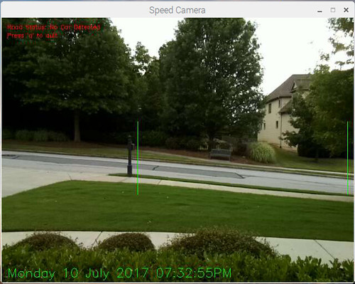
cv2.putText(image, "Road Status: {}".format(text_on_image), (10, 20),
cv2.FONT_HERSHEY_SIMPLEX,0.35, (0, 0, 255), 1)
if SHOW_BOUNDS:
#define the monitored area right and left boundary
cv2.line(image,(upper_left_x,upper_left_y),(upper_left_x,lower_right_y),(0, 255, 0))
cv2.line(image,(lower_right_x,upper_left_y),(lower_right_x,lower_right_y),(0, 255, 0))
# show the frame and check for a keypress
if SHOW_IMAGE:
prompt_on_image(prompt)
cv2.imshow("Speed Camera", image)
# Adjust the base_image as lighting changes through the day
if state == WAITING:
last_x = 0
cv2.accumulateWeighted(gray, base_image, 0.25)
state=WAITING;
key = cv2.waitKey(1) & 0xFF
# if the `q` key is pressed, break from the loop and terminate processing
if key == ord("q"):
break
# clear the stream in preparation for the next frame
rawCapture.truncate(0)
# cleanup the camera and close any open windows
cv2.destroyAllWindows()
The image window is only updated if no motion is detected. If the state is WAITING, the date, time and status is added to the current image. In line 345, the base_image is adjusted slightly to account for lighting changes in the monitored area. These changes result from clouds passing, the changing angle of shadows, blowing leaves, etc.The keyboard is checked for the press of “q” indicating the program should be terminated.

Hi Greg. This fills a wonderful void that I am sure would interest a lot of people with a similar issue…speeding neighbors. Do you sell this as a “ready to use” kit?
LikeLike
This exercise was meant to prove that speed measurement was possible with a Pi. It was a learning experience for me and I share it so that others can benefit from the result. Once you have a Pi with OpenCV and Python installed, you only need to download the program to use it. Also, selling it as a kit would imply the results are accurate, which may not be the case, since so many factors can throw off the final reading.
LikeLike
Hi there, based on this excellent guide I bought a PiCam, upgraded OS, installed OpenCV, which was time consuming, but interesting – but unfortunately could never get the code to run. So I looked elsewhere and found there’s an iOS app that does much the same and works really well:
https://itunes.apple.com/gb/app/speedclock-video-radar/id400876654?mt=8
Hope that’s ok Greg – don’t want to detract from your excellent project!
LikeLiked by 1 person
Sorry to hear you couldn’t get the code to run. If you post questions here or on the carspeed github site, someone may be able to help you. The app looks interesting, and seems to use the same concept, but where is the fun (and education) in buying an app you can create yourself?
LikeLike
hi greg i don’t know if you still monitor or get these replies but i was wondering if it possible to set up a 2nd monitoring area and track both areas ?
LikeLike
Since there was a bug in the initial version, I’ve replaced it completely. WordPress doesn’t give me a way to start a new comment thread. However, feel free to start a new topic on the Carspeed gitbub site if you would like. I’ve closed the existing issue threads on github so the all new comments or questions have a starting point after the update.
LikeLike
Hello how do I make the rectangle I draw rotate and make the measurement when the road is vertical or horizontal or diagonal
LikeLike
Carspeed can only measure cars passing horizontally, perpendicular to the camera. If the camera is perpendicular to the road, but the the road isn’t horizontal, just rotate the camera to make it horizontal. If that isn’t satisfactory, you will need to enhance the program to track the motion of an object at an angle and calculate its speed.
LikeLike
Hi Gregtinkers, I have two doubts:
1: how do I make the caption of the image in high resolution ?, Example: when I do a manual capture “with RPi_Cam_Web_Interface of silvanmelchior”, the captured image comes out in high resolution and weighs 2.44 mb, if I configure it in “Image Res: 2592 x 1944 “and the clear image comes out, and the plate is visible. In the same way as I do for “carspeed.py”, make the capura of the image in good resolution with the intention of reading or distinguish also the plate ?. Observe that “carspeed.py”, your vehicle weighs 256 kb, how or where do I to make it look clearer?
2. How do I make a rotation of 90 or 270 degrees of the camera through “vs.camera.rotation”, so that I can handle the rectangle drawn horizontally, without having to move or rotate the camera physically?
LikeLike
You can define the size of the image in lines 65 and 66, however a higher resolution slows processing which makes the results less accurate. Also, if you are trying to capture the plate at the same time, the vehicle is not perpendicular to the camera. That means the speed calculations will not be accurate. The image can be rotated using opencv. Take a look at this website http://docs.opencv.org/3.0-beta/doc/py_tutorials/py_imgproc/py_geometric_transformations/py_geometric_transformations.html
Rotating the image will change the monitored area, so I am not really sure this will be of help to you.
LikeLike
Unfortunately unreliable
This is a very interesting project but unfortunately about 15% of the cars going from left to right get measured wrong here. The speed is much to high, sometimes rediculous high.
I live in a narrow road with a speed limit of 30 km/h (approximately 20 mph). But this is the old main road through the small village I live in and it is absolutely straight and the shortest connection between two inter-city routes. So many cars drive too fast and I wanted to get some numerical values. Unfortunately the output of this program is so unreliable, that I it is of no use for me 😦
When I look at the shell window, I see the different speed readings the program takes for every passing car and the values differ from -12 to 60 and have all values in between. In most cases the value in the photo is quite close to what I would have guessed but in too many cases the speed is obviously complete wrong.
Can I somehow “see” what the image tracking tracks? I’m only 13 meters (39 feet?) away from the road and usually a car passes my window in about 0.8 seconds. Are these values a problem in any way? The background of the picture is mostly a house on the other side of the road.
It would be useful to see the captured frames and the reference point, that was taken for the speed measurement.
LikeLike
Are you using a Raspberry Pi 3? How large an area in pixels are you monitoring? Did you change the camera resolution? Remember, image processing is taxing the pi to its limits, so being accurate 85% may be the best you can hope for. You are welcome to improve upon the logic to make it more efficient. You may want to check out this version which uses threads to speed up the image processing.
You can display the image at any point using the cv2.imshow command. During development I had several windows open to display the image transformations as they occurred.
LikeLike
Hello and thank you for your answer. I use Raspberry Pi 2 (don’t have a model 3 here). The area I’m monitoring is probably half of the picture width (there are some poles I didn’t want to have in the picture, because of that I use such small region). So width is something about 320 pixels. the height may be 20% – 25% of the width. A car fits into this window approximately 2 – 2.5 times in length.
I used your project because I thought it would be easier, faster and cheaper than this one: http://blog.durablescope.com/post/BuildASpeedCameraAndTrafficLogger/
Before I try to understand and modify your brilliant work, I will try to get informations about the precision I can expect from the radar approach.
LikeLike
Hello again,
it is weekend and so I spent some more time with this very interesting project. I observed another car, that was measured much too fast and had a look at the shell window.
As you can see, the first car was only tracked two times. But it wasn’t faster than approximately 40 km/h (25 mph), so quite normal speed. As far as I understand from the comments in the code, the saved picture should show the car, when it hits the border of the drawn frame. But this saved picture shows the front of the car in the middle of the drawn frame!
No Car Detected
Tracking
x-chg Secs MPH x-pos width
118 0.09 65 125 176
243 0.23 53 0 301
No Car Detected
Tracking
x-chg Secs MPH x-pos width
47 0.14 17 189 112
93 0.20 24 143 158
156 0.36 22 80 221
216 0.50 22 20 281
236 0.65 19 0 301
No Car Detected
Tracking
x-chg Secs MPH x-pos width
46 0.09 26 196 105
115 0.19 31 127 174
242 0.33 37 0 301
No Car Detected
Tracking
x-chg Secs MPH x-pos width
45 0.09 25 223 78
82 0.19 22 186 115
114 0.30 20 154 147
150 0.40 19 118 183
185 0.50 19 83 207
223 0.64 18 45 209
259 0.72 19 9 213
268 0.87 16 0 177
No Car Detected
Tracking
x-chg Secs MPH x-pos width
48 0.15 17 0 48
85 0.21 21 0 85
124 0.35 18 0 124
164 0.41 21 0 164
202 0.51 20 0 202
239 0.61 20 7 232
277 0.71 20 48 229
301 0.81 19 89 212
No Car Detected
LikeLike
The first vehicle must have been moving fairly quickly since it covered the monitored area in .14 second. The last two vehicles passed through the monitored area in .87 and .81 seconds respectively.
The image from the last complete reading is saved. Since a vehicle may have exited the monitored area on the last frame, it is the second from the last frame that is used. Since there were only two readings on that first vehicle, it showed the first frame.
Since you are fairly close to the road, try making the height of the monitored area smaller. The monitored area doesn’t need to completely contain the vehicle – a thin sliver passing through the monitored area is sufficient to detect. That may reduce the processing time and give you more frames for computing the speed.
LikeLike
Root cause of wrong measurements found
I modified the code in a way, that all cropped images are stored for fast cars in tracking state. In each and every wrong measurements two cars were involved. This was not visible on the single photos that are usually taken.
LikeLike
Good job sleuthing your issue – carspeed just isn’t able to handle multiple vehicles in the frame at the same time.
LikeLike
I’m very new to raspberry but I wanted to give your project a shot. I followed everything *I think to a T* and got it all done, when I tried to launch it the first time it couldn’t find cv2 so I ran these commands I found online and cv2 seemed to work after that:
sudo apt-get install python-opencv
sudo apt-get install python-scipy
sudo apt-get install ipython
Then I ran carspeed.py and I get this after I make my box and hit c
pi@raspberrypi:~ $ python carspeed.py
Image width in feet 30 at 30 from camera
Monitored area:
upper_left_x 64
upper_left_y 196
lower_right_x 604
lower_right_y 332
monitored_width 540
monitored_height 136
monitored_area 73440
Traceback (most recent call last):
File “carspeed.py”, line 228, in
(_, cnts, _) = cv2.findContours(thresh.copy(), cv2.RETR_EXTERNAL,cv2.CHAIN_APPROX_SIMPLE)
ValueError: need more than 2 values to unpack
pi@raspberrypi:~ $
If you have any idea I would greatly appreciate it. I haven’t the slightest idea what to do except completely start over and try again. Thanks!
LikeLike
It looks like you do not have the most recent version of opencv installed. The number of values returned from the findContours function changed in the newer version. Revise the (_, cnts,_) to (cnts,_) and I think it may work for you.
LikeLike
That worked! Awesome, now to wait for some light to give it a try. Thank you!
LikeLike
I’m seeing that its outputting pictures into the root and its going to load up fast on my street. Is there a way to output it so that it can be view lived on a webpage? Maybe overwrite to the same image name then autoupdate the page? I’m not really sure, just an idea, or even better a live image and a top 5 based on speed for the day.
Thanks!
LikeLike
Hello, my name is Mateus, I would like to know if I can use another camera or only Pi Camera. Do you have any email or phone number
LikeLike
Hello Mateus. Yes another camera can be used. However the logic in the program would need to be modified. Take a look at this website
and see if it helps you understand the changes that will be needed.
LikeLike
Can we use a ip camera ?
LikeLike
Possibly. The program is designed for a Picamera so it would require extensive changes. CarSpeed requires a resonably high frame rate and I don’t know what an IP Camera would provide. Give it a try and let us know the results.
LikeLike
Hi Greg,
This is genius. I am yet to give this a shot but I wanted to thank you for posting this. I am very new to computer vision and writing code. I’m undertaking a project at university where I plan to estimate velocity but for sprint performance. I will be applying a similar method, using stereo vision, and via the horizontal plane. I look forward to keeping you updated and will most likely prompt you with a few questions in the near future 🙂
Cheers,
Adam
LikeLike
I had carspeed.py running before (the old version).
Now after reinstalling raspbian and followng the tutorial you linked from pyimagesearch I always get:
(cv) pi@raspberrypi:~/carspeed.py $ python carspeed.py
Traceback (most recent call last):
File “carspeed.py”, line 4, in
from picamera.array import PiRGBArray
ImportError: No module named ‘picamera’
I have seen that another user had this issue on github but the steps involved did not fix it for me.
I have picamera installed when not working in the virtualenv.
“sudo apt-get install python3-picamera” returns:
(cv) pi@raspberrypi:~/carspeed.py $ sudo apt-get install python3-picamera
Reading package lists… Done
Building dependency tree
Reading state information… Done
python3-picamera is already the newest version.
0 upgraded, 0 newly installed, 0 to remove and 5 not upgraded.
When working outside of the virtualenv “cv” I can import “picamera” in the python3 shell:
pi@raspberrypi:~/carspeed.py $ python3
Python 3.4.2 (default, Oct 19 2014, 13:31:11)
[GCC 4.9.1] on linux
Type “help”, “copyright”, “credits” or “license” for more information.
>>> import picamera
>>>
How can I include python3-picamera in the virtualenv “cv”? sudo apt-get install python3-picamera says that it is already installed. Is this command checking the global site-packages or the virtualenv only?
LikeLike
forgot this:
On virtualenv “cv” I tried to import picamera to python shell:
(cv) pi@raspberrypi:~/carspeed.py $ python
Python 3.4.2 (default, Oct 19 2014, 13:31:11)
[GCC 4.9.1] on linux
Type “help”, “copyright”, “credits” or “license” for more information.
>>> import picamera
Traceback (most recent call last):
File “”, line 1, in
ImportError: No module named ‘picamera’
>>>
LikeLike
The odd thing is:
When running NOT in CV virtual enviroment and running “python carspeed.py” it works.
Albeit it runs on python 2.7!
LikeLike
It is difficult to diagnose this issue, but I suggest reviewing the comments on the pyimamgesearch page where several people had the same problem with cv2.
LikeLike
This is a great little program. I just started using it to see how many people on our private community drive close to our 15 mph speed limit. I’m not a programmer, but would it be difficult to code this program so that you could save the detection box parameters, and have it start at boot up, and run in the back ground?
Thanks for the code.
LikeLike
Saving the parameters would take some programming, but just hard-coding them into the program wouldn’t be difficult. After defining the monitored area, write down the coordinates as displayed in the “Monitored area:” In the program comment out lines 148 to 160 and add the following 4 lines after the area you commented out:
ix = your upper left x value
fx = your lower right x value
iy = your upper left y value
fy = your lower right y value
(ix represents the initial x value, fx represents the final x value as the square was drawn on the screen)
That will hard-code the monitored area parameters. Remember that once you have done this the camera cannot be moved.
Research running a program on the Raspberry Pi at startup. There are many resources on the web to help you..
LikeLike
Dear Sirs,
Great project!
Brings down the discussion on a facts and figures base!
Is there a specific PI-camera needed? I saw several different models. Maybe you can advice a part number or provide a link to the one you have used.
Since I cannot set it up like you stationary in a house, I like to work with a 30kAh battery pack and access the RPi3 bei VNC over WLAN. Will the maintenance of the motion detection area work this way? Maybe you have also experience about the power consumption?
Finally: Is it relevant to have the camera aligned to the point of measure in a certain way? I mean thinks like orthogonal to the street and also verticallay aligned orthogonal rather than sloping? What is typical failure of measurement?
Thanks again and: Well, well done!
Uwe
LikeLike
Any Pi Camera can be used. Just adjust the field-of-view in line 68 to match the field-of-view in the version that you use.
Yes, it works fine using VCN. I don’t know specifics about battery pack usage, but I powered a Pi for 6 hours using one and the battery still had plenty of charge left.
For reasonably accurate readings, the camera must be perpendicular to the road. You’ll need to experiment to see if the slope distorts the readings.
It was meant as a proof-of-concept, and is not extremely accurate by any means. Only one car can be tracked at a time and passing clouds, wind blown leaves and stay cats can corrupt the reading.
Have fun experimenting!
LikeLike
Thanks for your prompt and detailed replay, Greg!
I’ll give it a shot in our so called “play street” (speed limit at 6km/h, narrow streets, so at 99% 1 car at a time). Hope I can work out the tech. details soon 🙂
Like it much!
Cheers
Uwe
LikeLike
Hi Greg – thanks so much for this… exactly what I was looking for!
I have a Pi3 with PiCamera2. I have updated the constants accordingly for my setup. I am getting accurate results from left top right (+/- 1 MPH), but way off on the right to left measurements for some reason. From left to right, 25MPH is logged at 26MPH, but from right to left, it is logged at 16MPH. More pronounced at higher speeds -> 35MPH is logged at 20MPH from right to left, for instance – but still pretty accurate from left to right. Our house and road are on a slight decline, but I have tried aligning the camera so it is parallel with our road, playing with my capture area, etc. to no avail. Can you think of anything obvious for me to check? I feel pretty confident with my setup, especially because my left to right values are so close.
Here are my 25MPH results:
(From Left to Right):
Tracking
x-chg Secs MPH x-pos width
127 0.10 48 0 127
180 0.20 35 0 180
234 0.33 27 5 229
308 0.43 27 78 230
365 0.53 26 133 232
424 0.63 26 185 239
460 0.74 24 238 222
(From Right to Left):
Tracking
x-chg Secs MPH x-pos width
55 0.13 16 359 101
109 0.27 16 305 155
161 0.40 16 253 193
217 0.53 16 197 189
276 0.67 16 138 190
331 0.80 16 83 186
387 0.94 16 27 181
414 1.07 15 0 151
LikeLike
The pixel difference between the two tests is very small, but that generated a large speed difference. How far are you from the road and what resolution are you using?
LikeLike
Thanks again for the response – yeah, the Left to Right readings are consistently logged every 0.1 second, whereas the Right to Left readings are logged between .13 and .14 seconds.
LikeLike
Here are some pics:
Monitor Window:
https://www.flickr.com/gp/150908913@N06/1EX9K8
Left to Right Capture:
Right to Left Capture:
LikeLike
…sorry – here is the Monitor Window:

LikeLike
..the only thing that I can think is that the cars coming from right to left traverse the shade of the trees – maybe that is affecting the capture logic?
LikeLike
Also they are being split by your mailbox. Try excluding it from the monitored area.
LikeLike
Thanks for the response Greg. The camera is 50 feet from the middle of the road. I started with the 640×480 resolution and the mailbox excluded (same results though). I am now at 800×600.
LikeLike
Updated monitor window (with camera not rotated to compensate for slope in road…
LikeLike
Greg – I wound up setting up different distances for cars going left to right and those going right to left (each generating different ftperpixel values). Results are much better now.
LikeLike
Hey!
First of all, AWESOME PROJECT! This is amazing dude!
Now, to the question: Is there a way to place the camera in front of the road? I mean, I don’t have the possibility to measure fron the side, as there’s no much space from where I can place the camera to the road. Can I place it in front of the cars that come and go? If so, any chance you can point me in the right direction on the configuration?
Thanks in advance!
LikeLike
Measuring speed using a Pi Camera from the front would be difficult. You might want to check out this article from Make Magazine. for another approach.
The Mattel radar detectors are available on eBay for about the same cost as a Pi Camera.
LikeLike
newer install cod for opencv
http://www.pyimagesearch.com/2016/04/18/install-guide-raspberry-pi-3-raspbian-jessie-opencv-3/
LikeLike
I bought an “Arducam 5 Megapixels 1080p Sensor OV5647 Mini Camera Video Module”* along with a RPi 3. Do I need to get a lower megapixel camera or can you tell what I need to modify in the config file to make this work properly. Right now everything is installed and working except for blurred picture grabs. Thanks for the great program, I hope to help the overworked local police by giving them a time frame by which to observe the unlicensed pilots that are failing to maintain a proper altitude through my neighborhood. Thanks again.
Dom
*Still picture resolution: 2592 x 1944, Max video resolution: 1080p
If this gets posted twice, it said it was not posted the first time.
LikeLike
The issue is that the Raspberry Pi 3 has limited processing power. OpenCV will not be able to process frames fast enough to get a speed reading if it is working with too many pixels. Try reducing the resolution and just monitoring a limited area to see if that improves the results.
LikeLike
Thank you very much!
It works on mac!
Just calibration needed.
LikeLike
I am getting the following error when trying to launch the program
pi@raspberrypi:/home/tempt $ python carspeed.py
Image width in feet 77 at 76 from camera
OpenCV Error: Unspecified error (The function is not implemented. Rebuild the library with Windows, GTK+ 2.x or Carbon support. If you are on Ubuntu or Debian, install libgtk2.0-dev and pkg-config, then re-run cmake or configure script) in cvNamedWindow, file /home/pi/opencv-3.3.0/modules/highgui/src/window.cpp, line 587
Traceback (most recent call last):
File “carspeed.py”, line 130, in
cv2.namedWindow(“Speed Camera”)
cv2.error: /home/pi/opencv-3.3.0/modules/highgui/src/window.cpp:587: error: (-2) The function is not implemented. Rebuild the library with Windows, GTK+ 2.x or Carbon support. If you are on Ubuntu or Debian, install libgtk2.0-dev and pkg-config, then re-run cmake or configure script in function cvNamedWindow
what does it all mean? I went through the long process of installing openCV and it was a good install according to the tutorial you linked
LikeLike
I can only guess that you have a problem with the installation of opencv. The error points to libgtk2.0-dev and pkg-config missing. I’d start there.
LikeLike
please can you send the code to ali.imad@mail.com with USB webcam not Raspian
LikeLike
Sorry, I do not have a version of this program that uses a USB webcam.
LikeLike
Do you know how I can use V4L2 instead of PiCamera?
I’m not familiar with both libraries, plus I’m not a programmer or what ever 🙂
LikeLike
Sorry, I’ve only worked with the PiCamera, so I cannot assist you. Try investigating this link. https://github.com/dlarue/carspeed
LikeLike
Pretty job, man. I did my own setup and it works out of the box. Just did some small changes in code to present data in metric system and added few lines to send data to thingspeak. I observed some missed vehicles in low light. I mean I see (hear rather) car, in output I see Trackig message, few samples with time and position, but at the and there is “No Car Detected” and no csv entry and no picture saved. From the other hand i’ve got proper entry in thingspeak. Something weird and i have to investigate whats the cause.
BR, Bart
LikeLike
Hi folk! who know were I can buy similar system on the market… I have the same problem at the parking lot of my company
LikeLike
How do i detect the speed vehicle with opencv python ? which code should i use for it ? please help me
LikeLike
Duhan – the code is here:
https://github.com/gregtinkers/carspeed.py
LikeLike
Looks to be an awesome program. New to the Raspberry Pi and programming in general. I installed opencv and your program on a New Raspberry PI 3b+ that already has Python 2 and 3 installed. When I try to run your program it says ” can’t find ‘__main__’ module in ‘carspeed.py’. Any help would be appreciated.
LikeLike
There are a number of causes for that message – probably something to do with the way you created your copy of the program. Do a Google search and check your code for the possible errors.
LikeLike
Here is how I got mine working on a fresh install
version of
PRETTY_NAME=”Raspbian GNU/Linux 9 (stretch)”
NAME=”Raspbian GNU/Linux”
VERSION_ID=”9″
VERSION=”9 (stretch)”
ID=raspbian
ID_LIKE=debian
HOME_URL=”http://www.raspbian.org/”
SUPPORT_URL=”http://www.raspbian.org/RaspbianForums”
BUG_REPORT_URL=”http://www.raspbian.org/RaspbianBugs”
at command prompt
sudo apt update
sudo apt upgrade
sudo apt install git
sudo apt install python3 python-opencv
sudo apt install libatlas-base-dev libjasper-dev libqtgui4 qt4-qtconfig libqttest4-perl
works like a charm,
cheers
Pusy
LikeLike
i have a question for you .. i have a code to calculate the vehicle on the highway using opencv python. I want to add the speed of the vehicle into my code. but I am confused how to enter the code to calculate the speed of the vehicle in my vehicle count code .. can you help me to solve this problem? can i request your email? i will send my vehicle counter code to your email and you can add speed of each vehicle .. i need your help sir thanks.
LikeLike
CarSpeed calculates speed (s) by measuring the time (t) the vehicle takes to cross the image. If you know the distance the image covers (d), you can use the formula d / t = s.
LikeLike
can i ask your email ? i will send my code to you
LikeLike
Sorry, but I can’t write your program for you. If you are using openCV to count cars, you should be able to determine the time it takes the car to travel across the image. Use that time and the distance the image covers to calculate the car’s speed.
LikeLike
I downloaded your program today and got it running. I am getting consistent “No Car Detected” messages after every car. They track for a second, +/-, and speeds are listed. Any ideas where to look?
LikeLike
How far from the road are you and what speeds are you anticipating? Are no images being saved to the disk?
LikeLike
The camera is about 45 feet from the center line of the street, the car speeds range from 5 to 35 mph. There are pedestrians passing through. About 124 images have been saved, each with speeds written on them. But the terminal window shows “No Car Detected” for all of them. I will check for the .csv file in the morning.
LikeLiked by 1 person
If the program is saving images with speeds, it is doing what it was intended to do. The ‘No Car Detected’ is just the state the program returns to after a car has passed and been recorded.
LikeLike
The images are being saved, and the .csv file is being saved with appropriate contents. Thank you for your prompt replies
LikeLike
Hi Gregg, I haven’t got started on this project yet, and have it as an active project on my to-do list for a neighborhood safety project and wonder what I would do in addition to what you started to add another camera to record the license plate too. Then the car speed plus the license plate automatically upload to a public site with a pareto chart speeds, cars, plates would be difficult for law enforcement to ignore. And the pi set up would be cheaper than the devices cities and law enforcement pay for those displays on streets that show drivers their speed but do not log data.
LikeLike
This project was meant to demonstrate the capabilities of the Pi and OpenCV. It isn’t designed or calibrated for speed enforcement (or public shaming.) It is not sufficiently accurate for that purpose. However it has been used to provide evidence that a street has a speeding problem to encourage police to increase surveillance.
That said, you could add a second Pi and camera that would record an image of the front or rear of a vehicle. That Pi would need to communicate with the one running the Car Speed Detector program, which would trigger the license plate camera when a car’s speed exceeded your speed threshold. CarSpeed works best when it is 50 to 100 feet from the road, so I can foresee some technical issues with the communication link to the license plate camera.
LikeLiked by 1 person
Thanks Greg. I’m so noob I assumed the Pi could have multiple camera inputs. I see that as your name suggests, tinkering is a necessary to learn capabilities of Pi (as we learn by doing in other aspects of our lives).
LikeLike
Traceback (most recent call last):
File “/home/pi/speed.py”, line 209, in
gray = cv2.cvtColor(gray, cv2.COLOR_BGR2GRAY)
cv2.error: OpenCV(3.4.4) /home/pi/packaging/opencv-python/opencv/modules/imgproc/src/color.cpp:181: error: (-215:Assertion failed) !_src.empty() in function ‘cvtColor’
I am getting error
LikeLike
Having a lot of fun tinkering with this! Quick question.. where in the code is the part where the last frame minus 1 is the frame that is saved (so you don’t lose the image of the car in the save as it has left the detection zone)? On that image also it would be great to get a box or a dot or something over the detected vehicle in the saved image (to try and human filter out false readings – ie, look back at a high reading and see that the red dot is actually on a something other than a vehicle). Finally, if i crank up the framerate on a PI3 do i need to mod the math?
LikeLike
The last frame is displayed, but it isn’t include in the speed calculation. The speed from the previous frame is displayed (line 313 saves the value for use on the image). You can use a higher frame rate, but the processing does take some time, so a high frame rate may just mean more frames are skipped. No math changes required. If you want to add a dot, or draw a rectangle around the detected vehicle the values (x,y,h,w) can be used, Those are the parameter of the largest contour that was found. I think the code to draw a green rectangle around the car would be cv2.rectangle(image,(x,y),(x+w,y+h),(0,255,0),2) but don’t hold me to that as I cannot test it. I’d suggest reviewing pyimagesearch.com as it is a great resource to learn about image processing.
LikeLike
I’m going to try to get this working on a PC with USB webcam. The extra processing power should be useful, and I intend to create a data log for later statistical analysis. Apart from figuring out how to read the camera, is there anything else that would be different?
LikeLike
Not having tried to do that, I ‘ll let others reply. Please share your results here.
LikeLike
I ended up finding another project that had webcam as an option…
https://github.com/pageauc/speed-camera/wiki
However I couldn’t get stable results, I got variable speeds for the same vehicle across the frame. It does have a cool way to calibrate though, you capture an image of a vehicle, look up it’s length and record how many pixels that length occupies.
LikeLike
I updated Greg’s software to work with a webcam using a –use-webcam option. The code is on github – https://github.com/dlarue/carspeed
LikeLike
a little hackery but you have to look for the 2 places with “#rPi” and comment out the rPi specific lines after the comment then uncomment the webcam versions above the line. Second #rPi location you want to use “while True:” instead of the “for frame….” line.
LikeLike
Here is a link to my fork which adds webcam support, automatic saving of the monitoring area in a CSV file, the –config option to load the monitoring area file, the “headless” option for running from commandline and via ssh along with setup to run in systemd daemon mode.
https://github.com/dlarue/carspeed
LikeLike
That’s great! Thanks for sharing.
LikeLike
Hopefully others will find it useful. One thing I just found out today was that OpenCV v4 was just released and when built on the rPi it is 30% faster than previous releases because it uses NEON and other ARM hardware to improve performance.
I may look into that and see if it would be possible to add vehicle detection to reduce false positives and maybe track vehicles behind other vehicles.
LikeLike
Hello Greg and thanks for this great project, I suffer from the same symptom you did and everybody else here, so going to give it a shot. I have a RPi 3 and need to buy a PiCam – can you tell me if this would work? if not, which do you recommend? https://www.amazon.com/Raspberry-Megapixels-Degrees-Acrylic-Official/dp/B07PQSCX55/ref=sr_1_8?keywords=pi+camera&qid=1559737344&s=gateway&sr=8-8
Thanks!
Motti
LikeLike
Yes, any of the official Pi cameras or the knock-offs should work. The only issue is the quality of the image, but for this application, a high quality image isn’t necessary. Have fun with the program!
LikeLike
Hi Greg,
Thanks so much for the help.
Installing opencv was somewhat a hassle, especially when the pi distro comes with python2.7 already installed, anyway, I got that part and now when running carspeed.py I get the following, any ideas? does this mean that the camera itself isn’t working?
Image width in feet 6 at 6 from camera
mmal: mmal_vc_port_enable: failed to enable port vc.null_sink:in:0(OPQV): ENOSPC
mmal: mmal_port_enable: failed to enable connected port (vc.null_sink:in:0(OPQV))0x18c03e0 (ENOSPC)
mmal: mmal_connection_enable: output port couldn’t be enabled
Traceback (most recent call last):
File “carspeed.py”, line 119, in
camera = PiCamera()
File “/usr/lib/python2.7/dist-packages/picamera/camera.py”, line 433, in __init__
self._init_preview()
File “/usr/lib/python2.7/dist-packages/picamera/camera.py”, line 513, in _init_preview
self, self._camera.outputs[self.CAMERA_PREVIEW_PORT])
File “/usr/lib/python2.7/dist-packages/picamera/renderers.py”, line 558, in __init__
self.renderer.inputs[0].connect(source).enable()
File “/usr/lib/python2.7/dist-packages/picamera/mmalobj.py”, line 2212, in enable
prefix=”Failed to enable connection”)
File “/usr/lib/python2.7/dist-packages/picamera/exc.py”, line 184, in mmal_check
raise PiCameraMMALError(status, prefix)
picamera.exc.PiCameraMMALError: Failed to enable connection: Out of resources
Thanks,
Max
LikeLike
Test the PiCamera with:
raspistill -o testshot.jpg
to verify it is working. I’ve failed to get the ribbon cable seated some of the times I have installed the camera.
I hope the 6 ft from camera was for testing – the farther the camera is from the road, the more readings it makes to compute accurate speeds. I was testing at about 60 feet. If the camera is too close to the road, the car will traverse the field of view too quickly.
LikeLike
don’t forget to enable the camera interface using ‘sudo raspi-config’ and triple check the ribbon cable including installing it into the correct connector.
LikeLike
Hey Greg,
First of all, let me say, I truly appreciate you taking the time, still reviewing this and helping folks, thanks thanks thanks!
Now, it seems like I suffered from too many python installs on my RPi, messed up opencv and more, so I am going to start fresh, before I do, I had a couple of questions for you:
1. I followed the thread you mentioned here http://www.pyimagesearch.com/2015/10/26/how-to-install-opencv-3-on-raspbian-jessie/ from Adrian Rosebrook to manually install opencv, while troubleshooting my issues I found that maybe you can already install opencv today simply by using python -m pip install opencv-python? does this get the same outcome? is it OK to use instead of the manual process of building the app and installing manually?
2. Adrian Rosebrock suggests creating a virtual env for the install (cv) and all runs from there, is there a need for this? or can one just install opencv and use it in the pi home folder?
3. Lastly, I’ll google this, but can I somehow remove all old python instances from the RPi and have only 3.5 installed? I want to run the carspeed.py with opencv4.1.0 and python3.5, the multiple python instances I had on my RPi confused me.
BTW, I checked my Picam cable and made sure it’s now connected properly, and I can capture an image using raspistill, going to start fresh once I see your reply and hopefully it works this time 🙂
Thanks and sorry if dumb questions,
Max
LikeLike
1) I haven’t updated the installation instructions, or tested the program on Raspbian Stretch, which you probably should be using today. Here is a link to those instructions
https://www.pyimagesearch.com/2017/09/04/raspbian-stretch-install-opencv-3-python-on-your-raspberry-pi/
I haven’t tested other installation methods – Adrian Rosebrook seems to know his stuff.
2,3) Yes, I recommend the virtual environments to organize the installations of Python and OpenCV. That should reduce the confusing version conflicts.
LikeLike
–UPDATE–
Greg, all is working!
So, as I mentioned, I started from scratch, re-flashed my raspbian and started over.
Since I didn’t need my RPi for anything else except this project (or will re-flash if need be) I gave up the virtual environment and compiling openvcv manually, simply followed this newer thread from Adrian Rosebrock and installed opencv using pip3.
Then, running your app with python3.5 carspeed.py (after tweaking the file with the right params) I can report that all looks good and running, I captured multiple cars with different speeds, images are stored, excel is generated, all is good, the only thing I am not sure about yet is how accurate the speed captured is, I might research on doing this again with opencv4.1.0 as the default installed with pip was 3.4.4
BTW – I also configured my RPi to have x11vnc start on boot, so I controlled everything from inside the house, instead of having to do it all outside.
Anyway, thanks again for everything Greg and thanks for putting this together! the need came since our street has no sidewalks and people speed here like crazy, my kids go to school every day using the road, the county police claimed they have no resources to send to check this, so maybe now that I can show them some lists of speeding cars, they will make the effort, afterall this could be revenue generating.
Thanks again
Max
LikeLike
The speeds recorded are in the ballpark of the speed of the car. You can test this by driving by at a set speed and seeing what is recorded. I hope that it helps to document the speeding problem on your road. Let us know how it goes.
LikeLike
as Greg stated, you can document/prove accuracy by driving your own car, noting the time and validating the speed. I recommend setting cruise control if you can as I had a tough time keeping a steady 25 right when needed. I had to do 3 passes just to be sure it was close. ie pass 1 I knew I was slightly over 25 so when I saw 27 it seemed correct. 2nd time was under 25 but 20 seemed a bit too low. 3rd time was closer to 30 and IIRC it showed 32 which was close and I estimated +/- 2-3MPH was good enough. Especially since it recorded cars doing > 40 MPH most of the time. You could even take a picture of your speedometer so the timestamp on your photo proof matched the time of the measured proof.
Look at my fork on github for how I coded it to work without any GUI at all after using the GUI once to setup the trigger area.
LikeLiked by 1 person
Also, accuracy could be improved by using a separate distance value for the near and far lanes. (Additional programming required 🙂
LikeLiked by 2 people
What’s your fork Doug? this has been forked 71 times! 🙂
LikeLike
It was posted in a previous comment but I’ll repost the link here too – https://github.com/dlarue/carspeed
LikeLike
Pingback: Car Speed Detection with a Raspberry Pi and a PiCamera – luca's trashbin
Hi Greg!
I have less than none experience using Pi platforms and I’m planning to use this application with a Pi Zero. What are your thoughts on this?
LikeLike
As long as the distance from the camera to the road is at least 50 feet, you define a thin (vertically) area to monitor and the cars are not going too fast – it should work. The pi zero doesn’t have the processing power of the standard P. And the standard Pi is working hard to keep up.
LikeLike
Can I load OpenCV with an image file instead of compiling per Adrians instructions? My compile is timing out on Buster.
LikeLike
I don’t know the answer. Give it a try and see if you can work with openCV within Python.
LikeLike
I got the Buster compile to run per instructions at https://www.pyimagesearch.com/2019/09/16/install-opencv-4-on-raspberry-pi-4-and-raspbian-buster/ followed by “$ make -j4” (which ran very quickly to previous fail point, then processed for sometime before failing again… thinking perhaps there was some kind of racing conditions with the multi threads… I then ran “$ make ” (one core). And YEAH!!!! it is now working!
I live on a 25MPH rd with 1000 cars a day and a lot of speeders… I set min to 40 to limit # pics recorded and still get 15 – 20. I don’t believe there are so many speeders going 80+MPH… Any idea to eliminate false positive 80+? without just filtering them out?
LikeLike
What is the distance between the camera and the center of the road? If the distance is too low, cars move through the frame too fast for a stable speed to be determined. At least 50 or 60 feet is good.
LikeLike
Love this project for my son and I to learn…I have a Pi3 and 32G c10 SSD. I’m concerned I may be getting bad high speeds due to fewer data points being captured and plan to filter them out (if fewer than 3 data points received indicate as bad data. I will try reducing monitored area too. Any other tips for eliminating incorrect measurements?
LikeLike
I filtered out “Too Low” and “Too High”. I wasn’t interested in people walking or riding a bike. I also found that “Too High” was often a bird or bug flying in front of the camera. It’s a great project! Y’all have fun!
LikeLike
Thanks for the comments. I am glad that you and your son have found it interesting. Moving the camera 50 to 70 feet from the road will provide a wider area for image capture, giving more data points. Birds and bugs will always be an issue – in an early test I had what looked like an empty image, but the speed registered as 3 MPH. Upon enlarging the picture I discovered it was a cat walking down the sidewalk.
LikeLike
I also filter out images with a velocity too high. They usually result from bugs/birds flying by too close.
I also calculate the area and aspect ratio of the moving objects, which allows me to classify the object somewhat. Like “pedestrian”, “car”, “truck”. It also allows to filter images above/below a certain aspect ratio. That usually results in my case from shadows of the object moving rapidly ahead of the object. This will result in an object that is very long compared to its hight.
LikeLike
I am constrained to moving camera back more than about 40ft. 3Qs: 1. Would increasing the horizontal size of the moused scan area result in more speed measures, thus fewer false measures? 2. Would counting number of speed measures during TRACKING and ID those with 2 or fewer as “invalid speed” be a solution? 3. would adjusting the execution path to reduce processing demand for each frame result in more speed measures?
It would be fun to really fix this but I don’t want to spend too much time debugging… my priority now that you have me hooked is to move onto learning more OpenCV…
LikeLike
1) Yes – make it is wide as possible, without including any stationary objects between the camera and road. Thinner will also speed up processing (within reason.) 2) Possibly. A Pi 4 might help too. 3) Squeezing more speed out of the program will always help. I’m not sure how much more can be done, but I welcome any improvements.
LikeLike
My camera is only about 20 feet from the street. The shorter the distance, the more important it will be to take directions of the vehicles into account. Cars on one side of the street will be closer to the camera than on the other side of the street and thus travel different distances. Either you take direction into account or use the distance to the middle of the street as an average and have less accurate measurements.
I also use a PI3 which gets me about 14 frames per second processed (approx. 70ms per frame). Assuming worst case conditions (1 frame until first detection, 3 valid frames for processing) gives a minimum time of 4x70ms= 280ms. At a distance of 40 feet, your field of vision is also 40 feet. So a vehicles maximum measurable speed would be 40 feet per 280ms or a stunning 96 mph!
I also spend a lot of time on trying to detect false measurements. Most of the time the root cause are insects / birds flying by very close. Also shadows of the vehicle do cause some false measurements (my camera looks down at quite a step angle, so it “sees” the shadows) and also dust/leaves that are pushed away in front of the car cause some erroneous measurements. I filter them by using a max velocity and also the ratio of the vehicle size (in case of shadows, the vehicle appears to be very wide compared to its hight). I figured that out by not only printing the speed on the image, but also the contour and the enclosing rectangle that had been detected.
LikeLiked by 1 person
dear Greg tinker
everything works well except line ‘228 ‘of the python car speed program
we are just children of 9 Th grade and have no one to help us.
HELP US PLEASE !!
LikeLike
Line 228 calls a function that locates the car within the image. The number of values returned by the function varies depending upon what version of Python you are using. Try changing the program line to
(cnts, _) = cv2.findContours(thresh.copy(), cv2.RETR_EXTERNAL,cv2.CHAIN_APPROX_SIMPLE)
and see if that solves the problem.
LikeLike
Hi, Having fun running this, one question though, at the distance I am at with the standard PiCam2 the track lengths are quite different, Left to Right is 76 feet, and Right to Left 61 feet. Is there a way to code a correction factor for one direction, i.e use Left to Right and apply modifier for Right to Left, in this case 1.23? I will have a shot myself but still coming up to speed with code.
LikeLike
Instead of having just the one DISTANCE (line 56) you would have to divide that into two distances, one for each direction. That would have to be done throughout the code. However, I think you could get by with just adding your factor in line 277 or 280. Where you have to add the factor depends on what value you used in the DISTANCE definition:
If you used 76 (L to R) in the definition, you have to divide abs_chg in line 280.by factor 1.23.
If you used 61 (R to L) in the definition, you have to multiply abs_chg in line 277.by factor 1.23.
LikeLike
Completely beginner here. Are there any constraints to running this on Windows 10 with a webcam?
LikeLike
As it is written, it only runs on a Raspberry Pi with a Pi Camera . However, there is no reason you couldn’t rewrite it for Windows using Python or something like the Processing environment, which also interfaces with OpenCV. Processing and Python, although different, are close enough in structure that most of the logic could be fairly easily modified. Tackle that and you will no longer be a beginner. 🙂
LikeLike
You can look for my post where I mention I modified it to work with a webcam. it’s not a 100% flip-a-switch process but I commented the one or two places where you comment out the rPi stuff and uncomment the webcam stuff.
Not for beginner programmers though.
LikeLike